
Circuit Diagram
Index 669
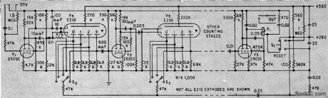
HIGH_SPEED_BCD_COUNTER
Published:2009/7/13 23:28:00 Author:May
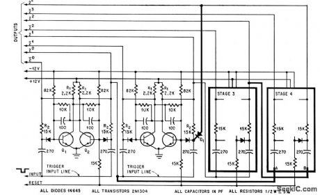
Elimination of capacitively coupled feedback increases operating speed to, maximum repetition rate of flip-flop stages. By modifying circuit as shown in heavy lines and adding diode D1, circuit returns to initial state at count of 10 rather than 16.-P. Ward. Modified Decade Counter Eliminates Components. Electronics.38:25,p74-75 (View)
View full Circuit Diagram | Comments | Reading(829)
COUNT_STORAGE
Published:2009/7/13 23:27:00 Author:May
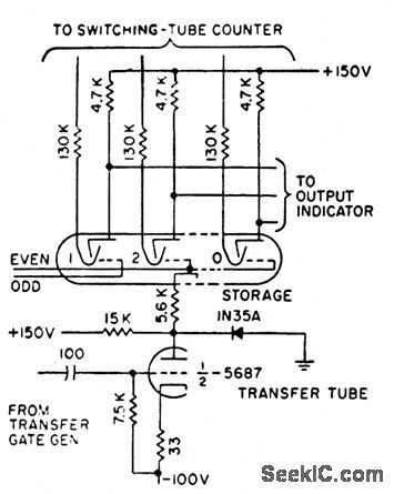


Magnetron beam-switching tube and transfer tube together serve to sample and store accumulated count and provide multioutput functions without stop-ping original count or losing input information during readout.-R. W. Wolfe, Decode Decimal Counter Speeds Printed Readout, Electronics, 31:3, p 88-90. (View)
View full Circuit Diagram | Comments | Reading(594)
BINARY_COUNTER
Published:2009/7/13 23:26:00 Author:May
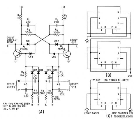
Basic binary circuit can be used alone as at A for counting up to 130 kc. Two circuits connected as at B give lip-fop operation, while one circuit with external connections as in C serves as bistable gate.-K. H. Brackney und D. R. Gosch, Pulse Comparator Circuit Measures Frequency Jitter, Electronics, 34:27, p 54-56. (View)
View full Circuit Diagram | Comments | Reading(1919)
ELECTRONIC_NOISEMAKER
Published:2009/7/13 23:25:00 Author:May
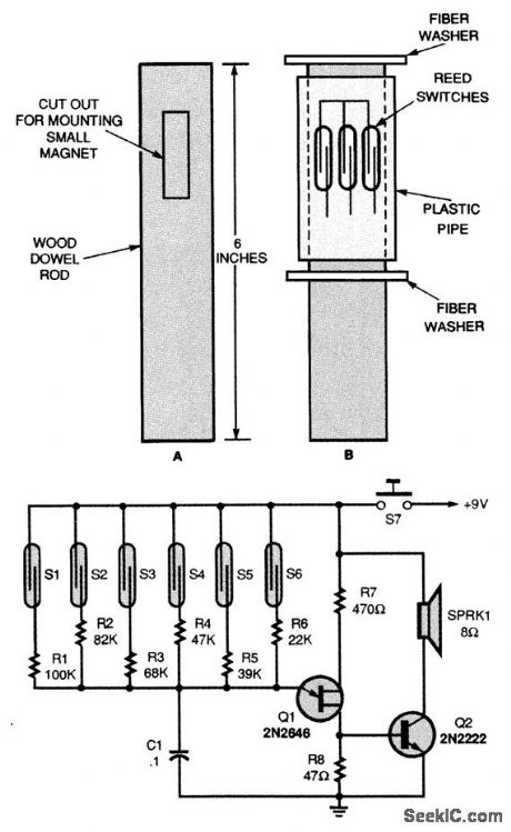
A single unijunction transistor, Q1, generates the different tones, and a general-purpose NPN transistor, Q2, raises the level to drive a small speaker. The six reed switches, S1 to S6, are mounted around the outside of the plastic pipe (Fig. B). As the pipe turns over the magnet, the reed switches open and close, tying different-valued resistors to the oscillator's frequency-control circuitry. It is also possible for two reed switches to be closed at the same time. When that happens, the output tone will be much higher in frequency than when only one switch is activated. The oscillator's frequency range can be lowered by increasing the value of C1, and raised by decreasing C1. To operate, just grab the noisemaker by the dowel rod and give it a twist to start the plastic case turning. (View)
View full Circuit Diagram | Comments | Reading(778)
SCANNER
Published:2009/7/13 23:24:00 Author:May

Provides eight combinations of four transmit and four receive frequencies under digital control using same four wires going to control head originally in four-channel commercial FM mobile transceiver. Also pro-vides scanning of up to eight receive channels. Uses SN7442 BCD-to-decimal decoder. Switch in original control head is rewired to count in BCD format. Carrier-operated circuit stops clock when signal is received during scanning, and readout device displays number of channel being received. Clock is UJT 02 with 500K pot varying scanning rate. Article covers construction and testing.-C. Durst, Scanning Adapter for FM Transceivers, 73 Magazine, April 1973,p73-78.
(View)
View full Circuit Diagram | Comments | Reading(1120)
ELECTRONIC_TROMBONE
Published:2009/7/13 23:23:00 Author:May
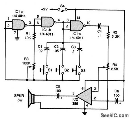
The heart of the trombone is R3, a slide potentiometer. Two gates of a quad two-input NAND gate, IC1-a and IC1-b, make up a simple audio-oscillator circuit, with R1, R3, C1, C2, and C3 setting the oscillator's frequency:The oscillator's output is buffered by IC1-c, which also supplies the drive signal for the power amplifier, IC2. The trombone's output level is set by R4. A slide handle, made of plastic or wood, should be attached to the slider of R3. The complete circuit, enclosed in a small plastic cabinet, with the three push-button switches, S1 to S3, mounted in a convenient location for playing. Just press one or more of the tone-control switches, S1 to S3, and work the slide. (View)
View full Circuit Diagram | Comments | Reading(1009)
3_A_BATTERY_CHARGER_FOR_Li-ION_OR_NiCd
Published:2009/7/13 23:22:00 Author:May

The LT1511 implements the constant-voltage/constant-curren t profile required for lithium-ion (Li-ion) batteries. It can also charge nickel-cadmium (NiCd) and nickel-metal-hydride (NiMH) batteries by using an extemal charge-termination method. Full charging current can be programmed by resistors or a DAC. An input current regulating loop on the LT1511 allows simultaneous equipment operation and battery charging without overloading the wall adapter. The charging current is automatically reduced to keep the wall adapter current within specified levels. (View)
View full Circuit Diagram | Comments | Reading(979)
PIN_DIODE_TR_SWITCH
Published:2009/7/13 23:22:00 Author:May

Solid-state TR switch operates at very high keying speeds and handles up to 100 W while transferring antenna between receiver and transmitter in accordance with transmitter keying demands. Uses Unitrode UM4004 PIN diodes to provide about 0.2-dB insertion loss when forward-biased and about 30-dB isolation when reverse-biased. CR1 is forward-biased for about 45 mA DC and CR2 is reverse-biased by 124 V during transmit, for minimum loss in CR1 and maximum isolation in CR2. Circuit is designed to operate from collector of keying-circuit transistor in Touchcoder II (in dotted lines at lower left), but any source providing required T (transmit) and R (receive) DC voltages shown on diagram will key circuit. Article covers construction in detail.-J. K. Boomer, PIN Diode Transmit/Receive Switch for 80-10 Meters, Ham Radio, May 1976, p 10-15.
(View)
View full Circuit Diagram | Comments | Reading(2150)
COUNTING_UP_TO_100_KC
Published:2009/7/13 23:21:00 Author:May
Uses miniature gas-filled decade counters that provide visual indication of count along with high reliability. Schmitt-trigger input feeds mono between counter tubes. Can produce output after desired count if counter is initially reset to complement of the desired number.-K. Apel and P. Berweger, Miniature Gas-Filled Tubes For High-Speed Counting. Electronics. 33:8,p46-47. (View)
View full Circuit Diagram | Comments | Reading(697)
CURRENT_SUPPLY_FOR_RTTY_MACHINES
Published:2009/7/16 1:38:00 Author:Jessie

Suitable for powering an old Model 15 Teleprinter, this simple simple to construct. The 20-Ω pot adjusts loop current. (View)
View full Circuit Diagram | Comments | Reading(745)
STANDARD_MICROMODULE_LOGIC_GATE
Published:2009/7/16 1:38:00 Author:Jessie
Single-transistor gate can have maximum fan-in of 20 and maximum fan-out of 4. Power dissipation is 75 mw average, pair delay is 60 nsec, and rise time 30 nsec.-A. S. Rettig, Computers in the Front Lines: Micromodules Make if Possible, Electronics, 36:1, p 77-81. (View)
View full Circuit Diagram | Comments | Reading(581)
THREE_STAGE_ENCODER
Published:2009/7/16 1:38:00 Author:Jessie
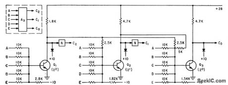
With 2N1499 transistors, settling time of encoder for simultaneous multiplier is less than 0.4 microsec, and maximum time to produce 8-bit product is about 1.2 microsec.-S. C. Chao, High Speed Encoding with Resistor-Transistor-Logic Circuits, Electronics, 35:6, p 48-51. (View)
View full Circuit Diagram | Comments | Reading(761)
AM_MIXER_IF_IC
Published:2009/7/16 1:37:00 Author:Jessie

Single National LM1820 chip provides all active stages for oscillator, mixer, IF amplifier, and AGC detector of superheterodyne AM broadcast radio. Omission of RF stage reduces cost at some sacrifice in sensitivity and stablity, along with more noise, but careful layout can minimize stability problems. Total gain is 88 dB. - Audio Handbook , National Semiconductor, Santa Clara, CA, 1977, p 3-4-3-8. (View)
View full Circuit Diagram | Comments | Reading(1165)
3_TO_15_V_dc_dc_CONVERTER
Published:2009/7/16 1:37:00 Author:Jessie

This circuit supplies 15 V at 30 mA from a 3-V source. The MAX630 IC is dc-dc converter, Q1 and D1 modify the duty cycle from 50% to 80% to optimize the output power. (View)
View full Circuit Diagram | Comments | Reading(705)
TRANSISTOR_SERIES_SWITCH
Published:2009/7/16 1:37:00 Author:Jessie
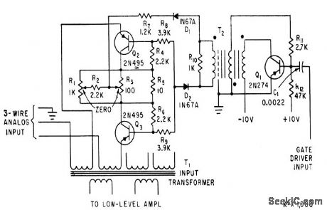
Two transistors back-lo-back in inverted connection serve as and gate between analog input from instrumentation transducer and input transformer of multiplexer. Gate driver receives key pulse from timing matrix.-C. E. Griffin, J. P. Knight, and J. H. Searcy, Low. Level Multiplexing for Digital Instrumentation, Electronics, 33:41, p 64-66. (View)
View full Circuit Diagram | Comments | Reading(809)
TICK_TACK_TOE_LOGIC
Published:2009/7/16 1:37:00 Author:Jessie

Neon lamps serve as diode gates and indicate positions and moves on game board. Thyratron-relay com bination serves as memory, while relays referee sequence to prevent two successive moves by either player.-C. E. Hendrix and R. B. Purcell, Neon Lamp Logic Gates Play Tick-Tack-Toe, Electronics, 31:25, p 68-69. (View)
View full Circuit Diagram | Comments | Reading(1796)
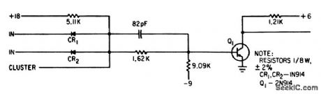
PULSE_SECIUENCE_DETECTOR
Published:2009/7/16 1:36:00 Author:Jessie
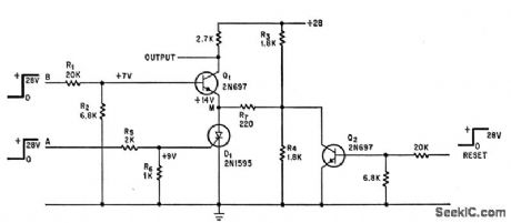
Output occurs only when event signal at A precedes event signal at B. Other sequences are ignored.-R. A. Wilson, Two Events, in Sequence, Produce Detector Output, Electronics,39:16, p 120-121. (View)
View full Circuit Diagram | Comments | Reading(605)
GATE_FOR_200_MC_INTERVAL_TIMER_
Published:2009/7/16 1:36:00 Author:Jessie
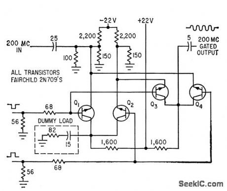
Two pairs of transistors can turn gate on or off in 1 nsec, from separate start and stop inputs. Only one transistor per pair conducts at a time.-C.S. Coffey, VHF Counter Measures Time Intervals Precisely, Electronics, 36:34, P 27-29. (View)
View full Circuit Diagram | Comments | Reading(752)
RESISTOR_TRANSISTOR_NAND_NOR_GATE
Published:2009/7/16 1:36:00 Author:Jessie
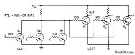
For integrated circuits, 100.ohm resistor in base lead of each transistor reduces waste curl rent, increases fan-out, and gives logic swing of 1 v.-A. E. Skoures, Choosing Logic for Microelectronics, Electronics, 36:40, p 23-26. (View)
View full Circuit Diagram | Comments | Reading(622)
HANDWRITING_READER
Published:2009/7/16 1:35:00 Author:Jessie
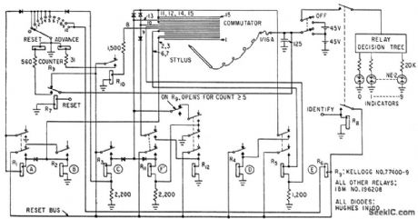
Spelled-out digits written with wire stylus on striated conductive surface are recognized by detecting risers, descenders, dots, word length, recrossings, and several other characteristics of spelled-out zero to nine, using only 12 relays, 8 diodes, and 10 neon indicator lamps. Accuracy is about 97% with the simple sequential logic used for recognition.-L. D. Harmon, Handwriting Reader Recognizes Whole Words, Electronics, 35:34, p 29-30. (View)
View full Circuit Diagram | Comments | Reading(637)
| Pages:669/2234 At 20661662663664665666667668669670671672673674675676677678679680Under 20 |
Circuit Categories
power supply circuit
Amplifier Circuit
Basic Circuit
LED and Light Circuit
Sensor Circuit
Signal Processing
Electrical Equipment Circuit
Control Circuit
Remote Control Circuit
A/D-D/A Converter Circuit
Audio Circuit
Measuring and Test Circuit
Communication Circuit
Computer-Related Circuit
555 Circuit
Automotive Circuit
Repairing Circuit