
Circuit Diagram
Index 679
PLL_WITH_DIVIDE_BY_N_CIRCUIT
Published:2009/7/13 21:37:00 Author:May
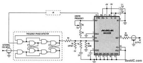
The MAX038 function generator IC can be used in a PLL system. To gain the advantages of a wider capture range and an optional divide-by-N circuit (which allows the PLL to lock onto arbitrary multiples of the applied frequency), you can introduce an external frequency-phase detector, such as the 74HC4046 or the discrete-gate version shown. Unlike phase detectors, which can lock to harmonics of the applied signal, the frequency-phase detector locks only to the fundamental. In the absence of an applied frequency, its output assumes a positive dc voltage (logic 1) that drives the RF output to the lower end of its range as determined by resistors R4 to R6. These resistors also determine the frequency range over which the PLL can achieve lock. Again, R4 to R6, C4, and RZ, determine the PLL's dynamic performance. (View)
View full Circuit Diagram | Comments | Reading(2912)
PLL_AM
Published:2009/7/16 2:28:00 Author:Jessie

Phase-locked loop of Signetics NE561B is locked to AM signal carrier frequency, and output of VCO in IC is used as local oscillator signal for product detector. Tuned RF stage will generally be required, along with good antenna and ground. Simple one-transistor audio amplifier will suffice for driving loud-speaker. Circuit can be adapted for other frequencies outside of broadcast band, from 1 Hz to 15 MHz, by changing values of CY and C1.-E.Kanter, PLL IC Applications for Hams, 73 Magazine, Sept. 1973, p 47-49. (View)
View full Circuit Diagram | Comments | Reading(1684)
31_m_SW_CONVERTER_FOR_AUTO_RADIOS
Published:2009/7/13 21:37:00 Author:May
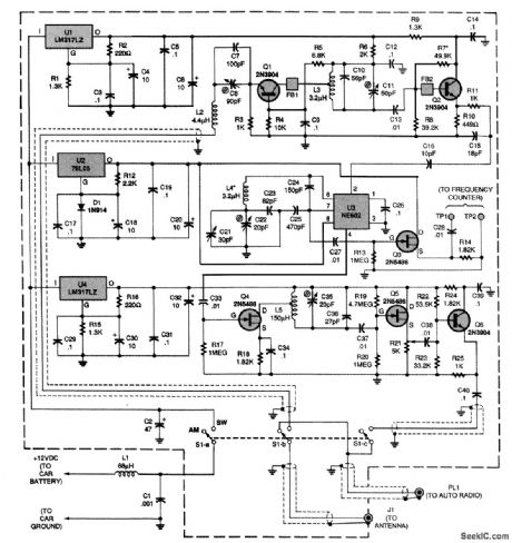
Power for the circuit is taken from the car battery and is dropped to the proper voltages for three sections of the circuit by three separate regulator ICs: U1, U2, and U4. Inductor L2 and capacitors C7 and C8 act as the circuit's antenna tuner. The tuned signal is fed to an input bandpass filter composed of L3, C10, and C11. An NE602 oscillator IC, U3, is used as a combined mixer and oscillator.That configuration is known as a series-tuned CoLpitts or Clctpp osciLlcttor, and is among the most temperature-stable variable oscillators. The 1710-kHz output filter consists of L5, C35, and C36.Each of the filters in the circuit was limited to a single LC section to simplify as much as possible the alignment of the converter. Transistor Q3 is a frequency-counter buffer that is used only during alignment. The gain of the converter is sufficient to overload the input of some receivers. Poten-tiometer R21 can be used to decrease the output level and prevent overload. (View)
View full Circuit Diagram | Comments | Reading(860)
60_MC_TETRODE_I_F
Published:2009/7/16 2:28:00 Author:Jessie
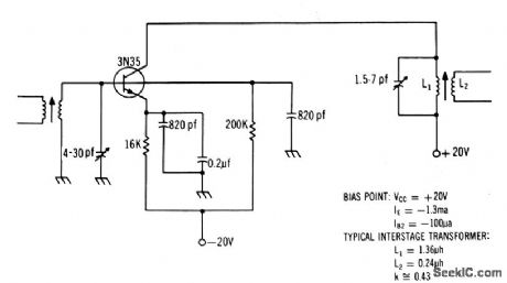
Use of 3N35 gives excellent agc characteristics, Stage gain is 12 db.-Texas Instruments Inc., Solid-State Communications, McGraw-Hill, N,Y., 1966, p 3. (View)
View full Circuit Diagram | Comments | Reading(718)
OPAMP_AS_CLIPPER
Published:2009/7/13 21:37:00 Author:May

Two zeners are used to clip both sides of AC signal. Clipping level is determined by rating of zeners used, which can be 6, 9, 12, or 15V depending on application. Ratio of R2 to R1 determines amplification. If long supply leads cause oscillation, connect 0.1-μF capacitors between ground and suρply ρins 4 and 7 as shown.-F.M. Mims,''Integrated Circult Proiects,Vol. 4,″Radio Shack,Fort Worth,TX,1977,2nd Ed,p 37-44. (View)
View full Circuit Diagram | Comments | Reading(1480)
KELVIN_CONNECTION
Published:2009/7/16 2:28:00 Author:Jessie
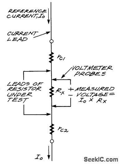
For low-resistance measurements, contact and test lead resistance introduce errors. This figure shows the way to avoid these. Current is applied through test leads, but separate leads are used to read voltage drop. (View)
View full Circuit Diagram | Comments | Reading(1026)
BACK_PORCH_KEYED_AGC
Published:2009/7/16 2:28:00 Author:Jessie

Composite of d-c coupling for dark scenes and a-c coupling for bright scenes, with agc referenced to back-porch (blanking level) rather than to sync tips, approaches ideal compromise for automatic control of tv picture.-L. Solomon, New Tubes and Circuits for Consumer Electronics, Electronics, 36:2, p 47-49. (View)
View full Circuit Diagram | Comments | Reading(647)
PULSED_GATED_30_MC_I_F_
Published:2009/7/16 2:27:00 Author:Jessie
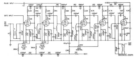
Control signals are fed to suppressor grids of early amplifier stages, to generate groups of i-f pulses for simulating radar scanning or for testing transient response of i-f circuits. Bandwidth is 1.2 Mc.-C. D. Rasmussen, Suppressor Gating for I-F Amplifiers, Electronics, 34:34, p 62. (View)
View full Circuit Diagram | Comments | Reading(617)
6_METER_FRONT_END
Published:2009/7/16 2:27:00 Author:Jessie

Developed for use as converter with any communication receiver having 1.65-MHz IF. Article covers construction and tune-up. Use of GE microtransistors permits miniaturization.-B. Hoisington, A Real Hot Front End for Six, 73 Magazine, Nov. 1974, p 88-90 and 92-94. (View)
View full Circuit Diagram | Comments | Reading(979)
70_MC_NEUTRALIZED
Published:2009/7/16 2:26:00 Author:Jessie
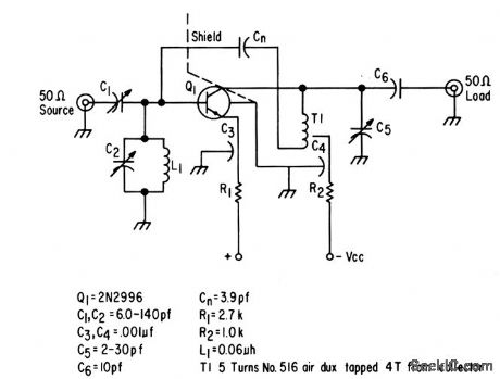
Designed to give maximum power gain in single stage while maintaining good stability. Noise figure is less than 3 db with power gain of 27 db.-Texas Instruments Inc., Solid-Stale Communications, McGraw-Hill, N.Y., 1966, p 313. (View)
View full Circuit Diagram | Comments | Reading(621)
BALANCED_MIXER
Published:2009/7/16 2:26:00 Author:Jessie
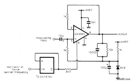
Uses CA3080 IC transconductance amplifier as precise low-frequency single balanced mixer with inherent carrier balance and accurately defined conversion gain. Binary divider IC halves oscillator frequency, giving carrier waveform having highly accurate unity mark-space ratio. Divided carrier is used to switch amplifier on as unity-gain voltage follower. Conversion loss is 4 dB.-R. J. Harris, Single Balanced Mixer, Wireless World, May 1976, p 79. (View)
View full Circuit Diagram | Comments | Reading(2065)
MILLIOHM_DMM_ASAPTER
Published:2009/7/16 2:26:00 Author:Jessie
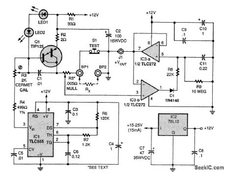
The circuit provides a 1.000-A constant-current pulse of 100-μs duration, at a 100-Hz repetition rate, to the unknown (RX) resistance, and provides an output voltage to your DMM of 1.000V per ohm of input resistance. Accuracy is better than ±1 percent up to 5.00 Ω, and the resolution using a 31/2-digit DMM is 100 μΩ. Extremely low resistance readings are limited only by the quality of the mechanical connections to RX, and the accuracy of the NULL setting. IC1 (a TLC555) provides the pulse timing to TIP125 transistor Q1, which is configured as a capacitive discharge current source. Capacitor CZ provides the current through R2, a stable metal-film or wire-wound resistor. Two red LEDs, LED1 and LED2, are selected to have a forward voltage drop of about 1.75V each (3.50V total) at a current range of 4 to 15mA, as provided in the circuit. Transistor Q1 has a dynamic Vbe of about 1.50 V, so the LEDs provide a 2.00-V reference across R2 with some temperature compensation. Integrated circuit IC3 (a TLC272) is configured as a peak detector. The 78L12 provides a regulated 12V to the circuit. The Rx, terminals, BP1 and BP2, must be heavy-duty binding posts; do not use test leads because that will introduce errors greater than the value of Rx. Resistor R5, the 0.005-Ω trimmer potentiometer, is simply a 2 1/2-in length of tinned, 24-gauge busbar wire, with the lead from pin 3 of IC3 terminated in a clip that will slide on the busbar. To calibrate the circuit, first use a heavy shorting bar between the input terminals, push S1 (TEST), and adjust R5 (NULL) for an output of 1.00 mV, or whatever value is convenient. You will have to subtract that NULL value from the actual readings. Next, replace the shorting bar with an accurate resistance, such as two 10.00-0, 1-percent resistors in parallel, and adjust R3 for the proper output (5.000 V). (View)
View full Circuit Diagram | Comments | Reading(2648)
TUNNEL_DIODE_GATE
Published:2009/7/16 2:25:00 Author:Jessie
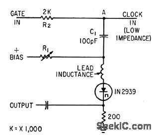
Impedance of tunnel diode is part of voltage divider, eliminating mood for a-c bridge in gate operating above 500 Mc.-F. W. Kantor, Tunnel-Diode Gate has Subnanosecond Rise Time, Electronics, 35:15, p 62-64. (View)
View full Circuit Diagram | Comments | Reading(664)
SIGNAL_LEVEL_CONTROLS_GAIN
Published:2009/7/16 2:25:00 Author:Jessie

Amplifier is used with nonlinear circuit elements to gel D-versus-log E characteristic approximating that of positive color film being scanned. When no signal is applied to grid of V1, all diodes in its cathode circuits are conducting, equivalent cathode resistance is lowest, and stage gain is highest. As signal level increases, diodes V4 through V9 successively stop conducting, with V9 turning off last to make stage gain a minimum.-R. lid. Farber and K. M. St. John, Scanner Analyzes Color Content of Movie Film, Electronics, 34:48, p 38-41. (View)
View full Circuit Diagram | Comments | Reading(580)
BASIC_NOR_GATE
Published:2009/7/16 2:25:00 Author:Jessie
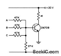
Transistor conducts heavily if any of inputs is raised from 0 to +12 V.- Transistor Mcnual, Seventh Edition, General Electric Co., 1964, p 178. (View)
View full Circuit Diagram | Comments | Reading(518)
SYNCHRONOUS_AM_DETECTOR
Published:2009/7/16 2:24:00 Author:Jessie

Input signal is applied to multiplier section of Exar XR-S200 PLL IC with pins 5 and 7 grounded. Detector gain and demodulated output linearity are then determined by resistor connected between pins 10 and 11, in range of 1K to 10K for carrier amplitudes of 100 mV P-P or greater. Multiplier output can be low-pass filtered to obtain demodulated output, For typical 30% modulated input with 10-MHz carrier and 1-kHz modulation, output is clean 1-kHz sine wave.- Phase-Locked Loop Data Book, Exar Integrated Systems, Sunnyvale, CA, 1978, p 9-16. (View)
View full Circuit Diagram | Comments | Reading(905)
FET_ANALOG_GATE
Published:2009/7/16 2:24:00 Author:Jessie

Series connection of chopper-type fet permits high-accuracy analog switching. Resistance of Q2 when on is only about 20 ohms, and drain gate leakage current is less than 0.1 nanoamp.-Six More Semiconductor Advances From TI (Texas Instruments ad), EEE, 14:8, p 120-121. (View)
View full Circuit Diagram | Comments | Reading(659)
30_MC_HYBRID_GAIN_CONTROL
Published:2009/7/16 2:24:00 Author:Jessie

Q2 acts as variable impedance to give emitter degeneration, which is a form of external gain control. Q2 also controls collector current of Q1 to give reverse gain control action, which is internal gain control. Gain control range is 33 db, with 2:1 change in bandwidth.-Texas Instruments Inc., Solid-State Communications, McGraw-Hill, N.Y., 1966, p 222. (View)
View full Circuit Diagram | Comments | Reading(680)
RF_METER
Published:2009/7/16 2:24:00 Author:Jessie
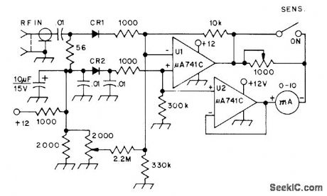
Simple square-law detector can detect and measure signals as low as -26 dBm, at microwatt levels. CR1 is biased with about 20 μA by opampU1 serving as low-impedance DC source. CR2 provides temperature compensation, and U2 serves as low-impedance reference for 10-mA meter. Diodes can be hot-carrier types or 1N914s.-W. Hayward, Defining and Measuring Receiver Dynamic Range, QST, July 1975, p 15-21 and 43. (View)
View full Circuit Diagram | Comments | Reading(1054)
ADJUSTABLE_RISE_AND_FALL_TIMES
Published:2009/7/16 2:23:00 Author:Jessie

constant-current source Q1-Q2 charges C3,while Constany-current sink Q3-Q4 discharges C3.-D. N Lee, Rise Time Adjustment Independent Of Fall Time, Electronics, 38:2 p76-78.
(View)
View full Circuit Diagram | Comments | Reading(907)
| Pages:679/2234 At 20661662663664665666667668669670671672673674675676677678679680Under 20 |
Circuit Categories
power supply circuit
Amplifier Circuit
Basic Circuit
LED and Light Circuit
Sensor Circuit
Signal Processing
Electrical Equipment Circuit
Control Circuit
Remote Control Circuit
A/D-D/A Converter Circuit
Audio Circuit
Measuring and Test Circuit
Communication Circuit
Computer-Related Circuit
555 Circuit
Automotive Circuit
Repairing Circuit