Basic Circuit
31_m_SW_CONVERTER_FOR_AUTO_RADIOS
Published:2009/7/13 21:37:00 Author:May | From:SeekIC

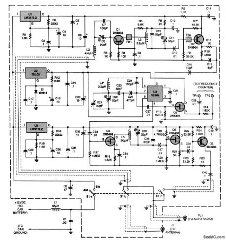
Power for the circuit is taken from the car battery and is dropped to the proper voltages for three sections of the circuit by three separate regulator ICs: U1, U2, and U4. Inductor L2 and capacitors C7 and C8 act as the circuit's antenna tuner. The tuned signal is fed to an input bandpass filter composed of L3, C10, and C11. An NE602 oscillator IC, U3, is used as a combined mixer and oscillator.That configuration is known as a series-tuned CoLpitts or Clctpp osciLlcttor, and is among the most temperature-stable variable oscillators. The 1710-kHz output filter consists of L5, C35, and C36.Each of the filters in the circuit was limited to a single LC section to simplify as much as possible the alignment of the converter. Transistor Q3 is a frequency-counter buffer that is used only during alignment. The gain of the converter is sufficient to overload the input of some receivers. Poten-tiometer R21 can be used to decrease the output level and prevent overload.
Reprinted Url Of This Article:
http://www.seekic.com/circuit_diagram/Basic_Circuit/31_m_SW_CONVERTER_FOR_AUTO_RADIOS.html
Print this Page | Comments | Reading(3)

Article Categories
power supply circuit
Amplifier Circuit
Basic Circuit
LED and Light Circuit
Sensor Circuit
Signal Processing
Electrical Equipment Circuit
Control Circuit
Remote Control Circuit
A/D-D/A Converter Circuit
Audio Circuit
Measuring and Test Circuit
Communication Circuit
Computer-Related Circuit
555 Circuit
Automotive Circuit
Repairing Circuit
Code: