
Circuit Diagram
Index 672
AM_HOMODYNE
Published:2009/7/16 0:07:00 Author:Jessie
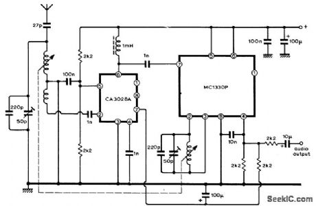
Circuit uses ICs to provide product demodulator that overcomes interstation tuning whistles or heterodynes by deriving local oscillator source from incoming signal carrier. This AM carrier is amplified before modulation is stripped off, and used in homodyne system in which convener output (IF signal) is the same as audio signal. Motorola MC1330P IC, originally developed as color TV video detector, is here connected as synchronous demodulator. RF amplifier IC is RCA CA3028A operating in cascode mode, with permeability tuning of input and RF choke and input of MC1330P together forming output load. Article covers circuit operation in detail and gives alignment procedures. Although developed for broadcast band, basic circuit can be adapted for communication and FM receivers as well.-J. W. Herbert, A Homodyne Receiver, Wireless World, Sept. 1973, p 416-419. (View)
View full Circuit Diagram | Comments | Reading(2713)
100_200_MHz_DIODE_RECEIVER
Published:2009/7/16 0:04:00 Author:Jessie
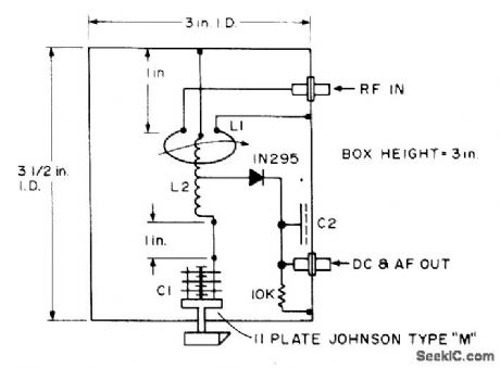
Hybrid tuned-diode version of basic crystal detector uses line cavity cut from sheet copper and soldered into box to give high Q up to 200 MHz. Useful for checking local oscillators around 135 MHz and transmitters around 147 MHz, along with 2-meter transmitters and transceivers. L2 is 4 turns air-wound 1/2 inch diameter and 1/2 inch long, with L1 as 1 turn adjustable around it. C2 is 1 x 2 inch brass plate with 0.005-inch teflon sheet with nylon bolts.-B. Hoisington, Tuned Diode VHF Receivers, 73 Magazine, Dec. 1974, p 81-84. (View)
View full Circuit Diagram | Comments | Reading(824)
144_MHz_PREAMP
Published:2009/7/16 0:02:00 Author:Jessie

Solid-state preamplifierfor 2-m band equals performance of best tube designs. Value of R1 is chosen for optimum gain versus noise figure. Two 500-pF feedthrough capacitors (FT) serve as convenient terminals for connection. Q1 is 2N2708, 2N4936, or equivalent. Article covers construction and tune-up. C. Sondgeroth , Really Soup Up Your 2m Receiver, 73 Magazine, Feb. 1976, p 40-42. (View)
View full Circuit Diagram | Comments | Reading(1149)
AUTO_RANGING_CAPACITANCE_METER
Published:2009/7/16 0:02:00 Author:Jessie
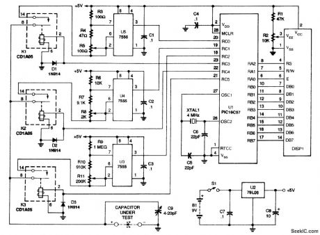
The schematic for the meter is shown. When switch S1 is closed, a 9-V battery, B1, supplies power to a 78L05 regulator, U2, and to filter capacitors C7 and C8. The result is a 5-Vdc supply for the rest of the circuit. Because the current draw is low, the 9-V battery will provide close to 40 1/2 hours of usage. A microchip PlC16C57, UI, is at the heart of the circuit. The internal EPROM is programmed with the meter's program. The circuit uses one of three 7555 CMOS timers, U3 to U5, to generate a pulse train. Microcontroller UI turns on one relay to connect the capacitor to one of the three timing circuits. The timer circuit, made up of U5, R3, R4, R5, and C1, has the lowest resistance and impedance; U4, with its surrounding components, has a medium resistance and impedance; and U3's circuit has the highest. All the timer circuits have two nominally equal resistors; one of them is the series combination of a fixed resistor and a trimmer potentiometer. That variable combination is for calibration. The high-impedance (1-MΩ) circuit is the default and is used for small-valued capacitors, the medium-impedance (10,000-Ω) circuit is used for medium-valued capacitors, and the low impedance (100-Ω) circuit is used for high-valued capacitors. When the capacitor under test is connected to the appropriate circuit, the microcontroller measures the frequency. A 4-MHz crystal, XTAL1, gives UI a 1-MHz internal clock frequency. The microcontroller can, therefore, count the number of pulses from the appropriate timer circuit in a known period of time. It then goes on to convert the frequency to capacitance using 32-bit, floating-point arithmetic, and displays the results on a 16×1 LLCD, DISP1, with the correct unit and decimal point. Capacitor C9 is connected in parallel to the capacitor under test to aid in final calibration and for stability. Diodes D1 to D3 protect the microprocessor from the back EMF of the relays' coils. Before you can use the PIC microprocessor in the meter, you have to program it. If you have the equipment to do that, you can obtain the software from the Gernsback BBS (516-293-2238). (View)
View full Circuit Diagram | Comments | Reading(2324)
150_MC_CLOCK_GATE_AND_DRIVER
Published:2009/7/16 Author:Jessie

When gale transistor Q1 (2N2368) is turned on, 200-Mc bandwidth amplifier Q2 is off to provide isolation and permit switching within one cycle of dock. Driver output goes to decade counter.-L. C. Drew, Using Microcircuits in High-Resolution Range Counters, Electronics, 36:47, p 31-33. (View)
View full Circuit Diagram | Comments | Reading(549)
SIMPLE_CAPACITY_METER
Published:2009/7/15 23:55:00 Author:Jessie
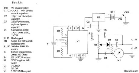
The figure shows the schematic diagram of the simple capacity meter. U1 (a 74LSOO logic chip), two resistors, a capacitor, and a crystal form a crystal oscillator operating near the marked frequency of the crystal. The RI' voltage is taken from pin 8 through isolation capacitor C3 and applied to the modified Wheatstone bridge circuit. R3 forms two arms of the bridge, with the arms ratio variable through the position of the wiper of R2. C5, which should be the stable capacitor specified in the parts list, and the unknown capacitor to be measured form the remaining bridge arms. R3 is adjusted for bridge balance, indicated by a dip minimum shown on microammeter M1, and the value of the un-known capacitor is indicated on the calibrated dial attached to R3. The instrument is powered by BT1, a 9-V battery, controlled by on/off switch S1. This 9 V is reduced and regulated by U2, a 78LO5, to the +5 V required by U1. (View)
View full Circuit Diagram | Comments | Reading(1784)
TWO_OUTPUT_SQUARE_WAVE_PULSE_GENER_ATOR
Published:2009/7/15 23:51:00 Author:Jessie

Pairs of control pulses are provided in sequence by silicon unijunction transistor in relaxation oscillator. Interval between pulses is determined by R3-C2. When C2 charges enough to trigger Q4, pulse fed to base of Q5 makes it conduct heavily; C3 charges and reset pulse is then developed across R4. Next, Q5 switches off, thereby feeding negative pulse to base of Q6 to switch Q6 off and make its collector voltage rise rapidly to form negative second pulse of pair.-C. D. Todd, Tunnel Diode Detects Currents Down to 100 Femtoamperes, Electronics, 36:14, p 33-37. (View)
View full Circuit Diagram | Comments | Reading(599)
SCANNER_FOR_2_METERS
Published:2009/7/13 23:15:00 Author:May
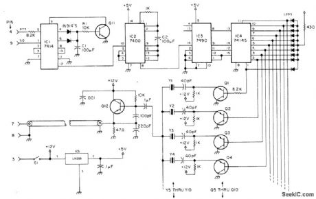
Developed for use with frequency synthesizer to scan transmit and receive frequencies of four receivers plus six other channels in 2-meter amateur band. Pin connections at left go to socket provided on lcom IC-230 synthesizer for connecting external VFO operating between 11.255 and 12.255 MHz. Q1-Q10can be 2N3638 or equivalent; Q11 is any NPN silicon such as 2N2102; and Q12 is 2N2102. LEDs operate from +12 V. In operation, scanner stops on active channel, and resumes scanning 5 s after channel goes off air. Article covers circuit operation, gives construction details, and tells how to calculate crystal frequency for each channel desired.-C. A. Kollar, Two Meter Scanner, 73 Magazine, June 1977, p46-48.
(View)
View full Circuit Diagram | Comments | Reading(1702)
HIGH_RESOLUTION_BRIDGE
Published:2009/7/15 23:49:00 Author:Jessie
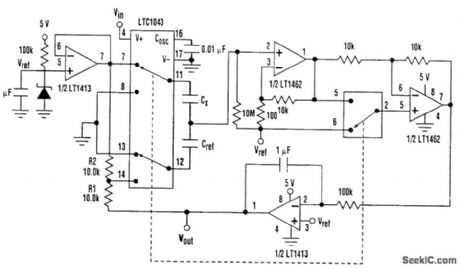
A JFET-input op amp (LT1462) amplifies the signal before demodulation for good noise performance, and the integrator's output is attenuated by RI and R2 to increase the sensitivity of the circuit. If △CX<<CX and Cref≈CX then
Vout-Vref≈Vref(△CX/Cref)[(R1+R2)/R2]
With Cref 50 pF, the circuit has a gain of 5 V/pF and can resolve 2 fF. Supply current is 1mA. The synchronous detection makes this circuit insensitive to external noise sources; in this respect, shielding isn't terribly important. However, to achieve high resolution and stability, care should be taken to shield the capacitors being measured. Bridge circuits are particularly suited for differential measurements. When CX, and Cref are replaced with two sensing capacitors, these circuits measure differential capacitance changes, but reject common-mode changes. CMRR for the circuit in this figure exceeds 70 dB. In this case, however, the output is linear only for small relative capacitance changes (View)
View full Circuit Diagram | Comments | Reading(970)
TR_SWITCH
Published:2009/7/13 23:13:00 Author:May

Simple transmit-receive switch uses 74122 retriggerable mono MVBR with clear and one NAND gate. When input of gate goes low (during key down or speech), transistor conducts and closes relay. Relay stays closed for period determined by delay pot, to maintain transmit condition between dots or dashes or between other pauses. Switch may be removed and any other TT'L-compatible input applied at point X.-B. Voight, The TI'L One Shot, 73Magazine, Feb, 1977, p 56-58. (View)
View full Circuit Diagram | Comments | Reading(0)
RING_TYPE_OSCILLATOR
Published:2009/7/15 23:47:00 Author:Jessie

After core-setting current is removed, pulse output of Q1 is followed by output of Q2 after delay of 100 microsec to 3 sec, depending primarily on input voltage and core size. No separate drive oscillator is required when used as ring counter.-J. M. Marzolf, Magnelic-Core Ring Counter Needs No Drive, Electronics, 35:12, p 52-53. (View)
View full Circuit Diagram | Comments | Reading(964)
MULTIPLE_OUTPUTS
Published:2009/7/15 23:42:00 Author:Jessie

Circuit Provides negative d-c output voltage and negative output pulses, using only single d-c source .Unijuncation-transistor lator Q1 provides positive pulses, while Q2 and Q3 together invert these and drive rectifier D1 that gives -5 v at 1 ma to drive low-power amplifier that may be used in same integrated circuit.-M. H. Hussain, Circuit Inverts D-C Voltage, Electronics, 38:19, p 100. (View)
View full Circuit Diagram | Comments | Reading(698)
WARBLE_TONE_OSCILLATOR
Published:2009/7/13 23:13:00 Author:May

Originally used for microwave transmitter testing, this warble oscillator produces a tone that jumps between two frequencies. (View)
View full Circuit Diagram | Comments | Reading(1092)
TUNNEL_DIODE_GIVES_FAST_MONO_RECOV
Published:2009/7/15 23:40:00 Author:Jessie

ERY-Time delay can be varied continuously over 100 to 1 range. Duty cycle is 0.9. Tunnel diode, connected between base and emitter of transistor switch, acts as current-controlled threshold detector.-P. Heffner, Tunnel Diode Multi Recovers Quickly, Electronics, 37:25, p 75-77. (View)
View full Circuit Diagram | Comments | Reading(653)
FULL_WAVE_CONTROL
Published:2009/7/13 23:13:00 Author:May

Uses triac to provide current for inductive load during both positive and negative alternations of AC source, with optoisolator providing complete isolation for logic control circuit. MDA920-4 diode bridge provides pulsating DC voltage for photo-SCR of optoisolator so gate current is supplied to triac for both halves of AC cycle.-T. Mazur, Solid-State Relays Offer New Solutions to Many Old Problems, EDN Magazine, Nov. 20,1973, p 26-32. (View)
View full Circuit Diagram | Comments | Reading(1699)
3_35_kHz_VARACTOR_TUNER
Published:2009/7/13 23:12:00 Author:May

Variable oscillator for 80-meter SSB transceiver is tuned by 1N594 diode. MPFl02 FET serves as source-follower buffer, With values shown, full excursion of R8 tunes oscillator from 3.045 to 3.545 MHz. Use well-regulated 12-V source. R9 allows synchronization of receive and transmit frequencies. K1 is 4PDT relay used for switching supply voltage and antenna from transmit to receive. L8 is 40 turns No. 32 on 1/4-in slug-tuned form.-W. J. Weiser, Integrated Circuit SSB Transceiver for 80 Meters, Ham Radio, April 1976, p 48-52. (View)
View full Circuit Diagram | Comments | Reading(811)
COUNTING_AT_6_KC
Published:2009/7/13 23:12:00 Author:May

Counts pulses received, displays count. and sets carry store when necessary.-M. E. Bond, Cold-Cathode Tubes as Triggers, Electronics, 38:7, p76-85. (View)
View full Circuit Diagram | Comments | Reading(554)
STABLE_SINE_WAVE_GENERATOR
Published:2009/7/13 23:11:00 Author:May
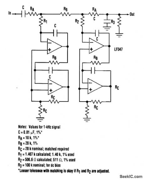

Semidigital circuits (e.g., crystal oscillators and dividers) can create square waves of very stable amplitude and frequency. Removing the odd harmonics is a reasonable task for a filter. The obvious solution, a narrowband filter, isn't acceptable because analog types are notorious for poor stability.Digital and semidigital types (e.g., switched capacitor) are better in this respect, but they add their own noise and harmonics. The task can be accomplished using the filter shown. Without R1 and R2, it is an active version of a five-pole passive low-pass LC ladder. This type has excellent amplitude stability in the passband, 30 dB/octave slope outside the passband, low component sensitivity, and a capacitor to ground at the output, which ensures continuous high-frequency rolloff and minimizes stray noise pickup. The rejection would be inadequate at the third and fifth harmonics, but notches at these frequencies can be created with just two more resistors, RI and R2. This turns the device into an elliptic-like filter. (View)
View full Circuit Diagram | Comments | Reading(890)
40000_CPS_DECADE_COUNTER
Published:2009/7/13 23:11:00 Author:May
Basic building block in counter is bistable mvbr which produces binary counts. Operates over wide range of operating voltages and temperatures.-Decade Counter is Flexible, Reliable, Electronics, 31:49, p 104-106. (View)
View full Circuit Diagram | Comments | Reading(753)
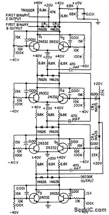
HYBRID_RING_COUNTER
Published:2009/7/13 23:10:00 Author:May
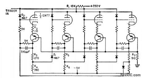
Counts reliably up to about 500 kc, with trigger amplitude of 4.5V All stages are identical.-G. A. Dunn and N.C. Hekimian. Tube-Transistor Hybrids Prove Design Economy. Electronics.32:23,p68-70. (View)
View full Circuit Diagram | Comments | Reading(701)
| Pages:672/2234 At 20661662663664665666667668669670671672673674675676677678679680Under 20 |
Circuit Categories
power supply circuit
Amplifier Circuit
Basic Circuit
LED and Light Circuit
Sensor Circuit
Signal Processing
Electrical Equipment Circuit
Control Circuit
Remote Control Circuit
A/D-D/A Converter Circuit
Audio Circuit
Measuring and Test Circuit
Communication Circuit
Computer-Related Circuit
555 Circuit
Automotive Circuit
Repairing Circuit