Measuring and Test Circuit
SIMPLE_CAPACITY_METER
Published:2009/7/15 23:55:00 Author:Jessie | From:SeekIC

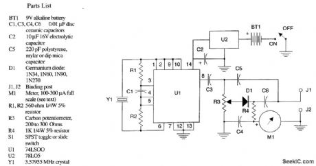
The figure shows the schematic diagram of the simple capacity meter. U1 (a 74LSOO logic chip), two resistors, a capacitor, and a crystal form a crystal oscillator operating near the marked frequency of the crystal. The RI' voltage is taken from pin 8 through isolation capacitor C3 and applied to the modified Wheatstone bridge circuit. R3 forms two arms of the bridge, with the arms ratio variable through the position of the wiper of R2. C5, which should be the stable capacitor specified in the parts list, and the unknown capacitor to be measured form the remaining bridge arms. R3 is adjusted for bridge balance, indicated by a dip minimum shown on microammeter M1, and the value of the un-known capacitor is indicated on the calibrated dial attached to R3. The instrument is powered by BT1, a 9-V battery, controlled by on/off switch S1. This 9 V is reduced and regulated by U2, a 78LO5, to the +5 V required by U1.
Reprinted Url Of This Article:
http://www.seekic.com/circuit_diagram/Measuring_and_Test_Circuit/SIMPLE_CAPACITY_METER.html
Print this Page | Comments | Reading(3)

Article Categories
power supply circuit
Amplifier Circuit
Basic Circuit
LED and Light Circuit
Sensor Circuit
Signal Processing
Electrical Equipment Circuit
Control Circuit
Remote Control Circuit
A/D-D/A Converter Circuit
Audio Circuit
Measuring and Test Circuit
Communication Circuit
Computer-Related Circuit
555 Circuit
Automotive Circuit
Repairing Circuit
Code: