Measuring and Test Circuit
AUTO_RANGING_CAPACITANCE_METER
Published:2009/7/16 0:02:00 Author:Jessie | From:SeekIC

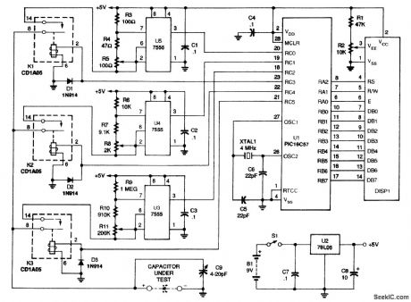
The schematic for the meter is shown. When switch S1 is closed, a 9-V battery, B1, supplies power to a 78L05 regulator, U2, and to filter capacitors C7 and C8. The result is a 5-Vdc supply for the rest of the circuit. Because the current draw is low, the 9-V battery will provide close to 40 1/2 hours of usage. A microchip PlC16C57, UI, is at the heart of the circuit. The internal EPROM is programmed with the meter's program. The circuit uses one of three 7555 CMOS timers, U3 to U5, to generate a pulse train. Microcontroller UI turns on one relay to connect the capacitor to one of the three timing circuits. The timer circuit, made up of U5, R3, R4, R5, and C1, has the lowest resistance and impedance; U4, with its surrounding components, has a medium resistance and impedance; and U3's circuit has the highest. All the timer circuits have two nominally equal resistors; one of them is the series combination of a fixed resistor and a trimmer potentiometer. That variable combination is for calibration. The high-impedance (1-MΩ) circuit is the default and is used for small-valued capacitors, the medium-impedance (10,000-Ω) circuit is used for medium-valued capacitors, and the low impedance (100-Ω) circuit is used for high-valued capacitors. When the capacitor under test is connected to the appropriate circuit, the microcontroller measures the frequency. A 4-MHz crystal, XTAL1, gives UI a 1-MHz internal clock frequency. The microcontroller can, therefore, count the number of pulses from the appropriate timer circuit in a known period of time. It then goes on to convert the frequency to capacitance using 32-bit, floating-point arithmetic, and displays the results on a 16×1 LLCD, DISP1, with the correct unit and decimal point. Capacitor C9 is connected in parallel to the capacitor under test to aid in final calibration and for stability. Diodes D1 to D3 protect the microprocessor from the back EMF of the relays' coils. Before you can use the PIC microprocessor in the meter, you have to program it. If you have the equipment to do that, you can obtain the software from the Gernsback BBS (516-293-2238).
Reprinted Url Of This Article:
http://www.seekic.com/circuit_diagram/Measuring_and_Test_Circuit/AUTO_RANGING_CAPACITANCE_METER.html
Print this Page | Comments | Reading(3)

Article Categories
power supply circuit
Amplifier Circuit
Basic Circuit
LED and Light Circuit
Sensor Circuit
Signal Processing
Electrical Equipment Circuit
Control Circuit
Remote Control Circuit
A/D-D/A Converter Circuit
Audio Circuit
Measuring and Test Circuit
Communication Circuit
Computer-Related Circuit
555 Circuit
Automotive Circuit
Repairing Circuit
Code: