Basic Circuit
ELECTRONIC_NOISEMAKER
Published:2009/7/13 23:25:00 Author:May | From:SeekIC

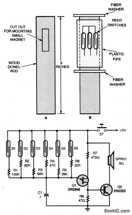
A single unijunction transistor, Q1, generates the different tones, and a general-purpose NPN transistor, Q2, raises the level to drive a small speaker. The six reed switches, S1 to S6, are mounted around the outside of the plastic pipe (Fig. B). As the pipe turns over the magnet, the reed switches open and close, tying different-valued resistors to the oscillator's frequency-control circuitry. It is also possible for two reed switches to be closed at the same time. When that happens, the output tone will be much higher in frequency than when only one switch is activated. The oscillator's frequency range can be lowered by increasing the value of C1, and raised by decreasing C1. To operate, just grab the noisemaker by the dowel rod and give it a twist to start the plastic case turning.
Reprinted Url Of This Article:
http://www.seekic.com/circuit_diagram/Basic_Circuit/ELECTRONIC_NOISEMAKER.html
Print this Page | Comments | Reading(3)

Article Categories
power supply circuit
Amplifier Circuit
Basic Circuit
LED and Light Circuit
Sensor Circuit
Signal Processing
Electrical Equipment Circuit
Control Circuit
Remote Control Circuit
A/D-D/A Converter Circuit
Audio Circuit
Measuring and Test Circuit
Communication Circuit
Computer-Related Circuit
555 Circuit
Automotive Circuit
Repairing Circuit
Code: