Basic Circuit
ELECTRONIC_TROMBONE
Published:2009/7/13 23:23:00 Author:May | From:SeekIC

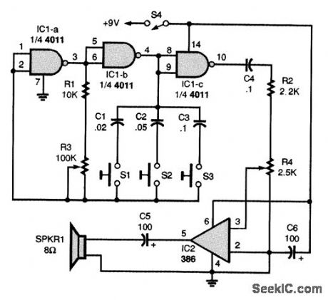
The heart of the trombone is R3, a slide potentiometer. Two gates of a quad two-input NAND gate, IC1-a and IC1-b, make up a simple audio-oscillator circuit, with R1, R3, C1, C2, and C3 setting the oscillator's frequency:The oscillator's output is buffered by IC1-c, which also supplies the drive signal for the power amplifier, IC2. The trombone's output level is set by R4. A slide handle, made of plastic or wood, should be attached to the slider of R3. The complete circuit, enclosed in a small plastic cabinet, with the three push-button switches, S1 to S3, mounted in a convenient location for playing. Just press one or more of the tone-control switches, S1 to S3, and work the slide.
Reprinted Url Of This Article:
http://www.seekic.com/circuit_diagram/Basic_Circuit/ELECTRONIC_TROMBONE.html
Print this Page | Comments | Reading(3)

Article Categories
power supply circuit
Amplifier Circuit
Basic Circuit
LED and Light Circuit
Sensor Circuit
Signal Processing
Electrical Equipment Circuit
Control Circuit
Remote Control Circuit
A/D-D/A Converter Circuit
Audio Circuit
Measuring and Test Circuit
Communication Circuit
Computer-Related Circuit
555 Circuit
Automotive Circuit
Repairing Circuit
Code: