
About SeekIC | Services | Payment | Advertisements service | Contact Us | Links
© 2008-2012 SeekIC.com Corp.All Rights Reserved.

Published:2009/7/16 13:07:00 Author:Jessie
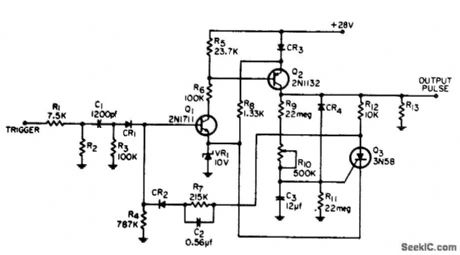
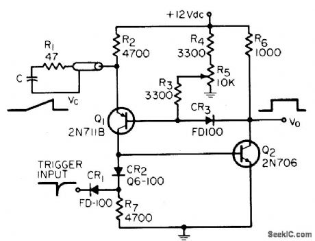
Output pulse width at collector of Q2 can be varied from 0.5 to 300 millisec. With suitable trigger, serves as one-shot for variety of uses.-Wide Range Variable Multivibrator, Electronic Circuit Design Handbook, Mactier Pub. Corp., N.Y., 1965, p 110. (View)
View full Circuit Diagram | Comments | Reading(663)
Published:2009/7/16 13:06:00 Author:Jessie
Addition of three diodes and one resistor to conventional monstable mvbr permits increasing value of timing resistor Rt without making circuit susceptible to false triggering.-H. Cohen, Eliminating False Triggering in Monostable Multis, EEE, 14:8, p 168. (View)
View full Circuit Diagram | Comments | Reading(584)
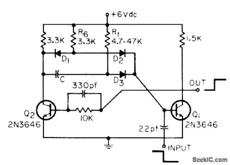
Published:2009/7/16 13:05:00 Author:Jessie
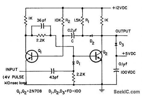
Has long delay time along with fast rise and fall times (each 30 nsec). Pulse amplitude is clamped at 5 V.-Fast Turnoff Monostable Multivibrator, Electronic Circuit Design Handbook, Mactier Pub. Corp., N.Y., 1965, p 69. (View)
View full Circuit Diagram | Comments | Reading(696)
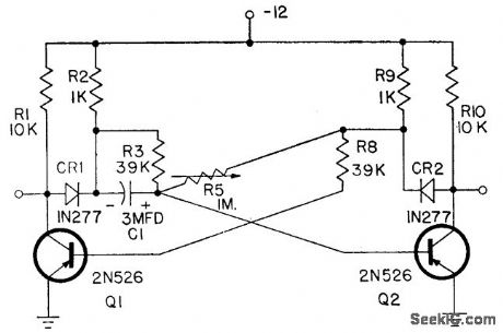
Published:2009/7/16 13:03:00 Author:Jessie

Simple astable circuit design eliminates external trigger, minimizing number of components. Voltage dividers R1 and R2 provide gate voltage for scr's. Both dividers start charging associated capacitors C2 until one scr breaks down, initiating oscillation. Used in converter power supplies.-W. B. McCartney and E. O. Uhrig, Actable High Power Multivibrator, EEE, 10:12, p 30-31. (View)
View full Circuit Diagram | Comments | Reading(975)
Published:2009/7/16 12:41:00 Author:Jessie

Used for automatic testing of computer memories under marginal drive currents, Error in memory causes monostable mvbr to generate pulse half as long as complele pass through storage, to make system track along error boundry. Npn transistors are 2N706 and the diode is 1N921.-J. E. Gersbach, The Great Shmoo Plot: Testing Memories Automatically, Electronics, 39:15, p 127-134. (View)
View full Circuit Diagram | Comments | Reading(685)
Published:2009/7/16 12:40:00 Author:Jessie

Complementary-symmetry one-shot supplies 1.4 W for 0.1 sec to relay coil on very low duty cycle, without drawing standby power. Used to discharge large 10-kv capacitor. -W. P. Mitchell, Power One-Shot, EEE, 13:6, p 68. (View)
View full Circuit Diagram | Comments | Reading(681)
Published:2009/7/13 Author:May

Suitable for use when frequency or some other critical parameter of load is not dependent on voltage. Developed for use in CMOS IC function generator.-R. Megirian, Ingegrated-Circuit Function Generator, Ham Radio, June 1974, p 22-29. (View)
View full Circuit Diagram | Comments | Reading(1074)
Published:2009/7/16 12:39:00 Author:Jessie
Advantages are high current gain, long pulse width with relatively small timing capacitance, and low dissipation when off. Pulse width is 11 sec. Drives 19.6K load.-J. M. Meuer, High-Gain, Long-Pulse Monostable, EEE, 14:4, p 41. (View)
View full Circuit Diagram | Comments | Reading(695)
Published:2009/7/12 23:59:00 Author:May

Feedback-type regulator holds magnet currents constant for control rods, at yalues set by R9 to 0.6 amp. When selected rods must be tripped for certain tests, regulator buses for these rods are connecled to -10V,to drop the rods. Ampliler uses +10V supply as reference to hold output at -2 v.-E. J.Wade and D. S. Davidson, How Transislor Circuils Protecl Alomic Reaclors, Electronics, 31:29, p73-75. (View)
View full Circuit Diagram | Comments | Reading(543)
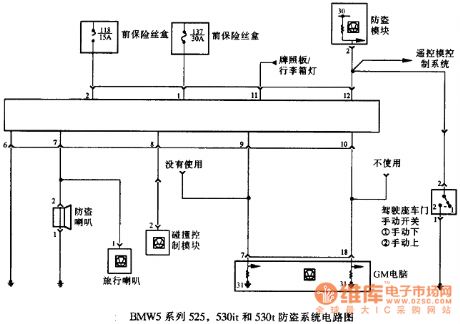
Published:2011/7/19 10:35:00 Author:Nancy | Keyword: component location, anti-theft, BMW5 series
View full Circuit Diagram | Comments | Reading(494)
Published:2009/7/16 12:37:00 Author:Jessie
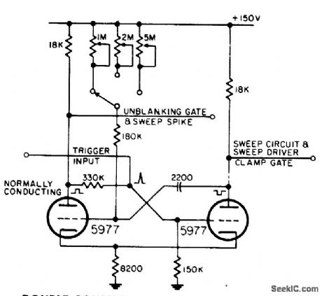
Uses both cathode and plate-to-grid coupling, with gate length changed by switching of potentiometers. Used in radar to provide gate during which display sweep is generated, along with gates for waveforms that must be coincident with display sweep.-NBS, Handbook Preferred Circuits Navy Aeronautical Electronic Equipment, Vol. 1, Electron Tube Circuits, 1963, p N10-3. (View)
View full Circuit Diagram | Comments | Reading(514)
Published:2009/7/12 23:55:00 Author:May
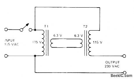
Connect 6.3-V filament transformers back.to-back as shown to get 230 V when step-up transformer is not available. 115-V windings must be phased properly in series; if wrong, output voltage will be zero.Output power rating at 230 V is somewhat less than twice the power (E x I) rating of smallest filament transformer. If 6.3-V 10-A transformers are used, power rating would be about 1000 W (less than 2 x 6.3 x 10).-A. E. McGee, Jr., Cheap and Easy 230 Volt AC Power Supply, 73 Magazine, Aug. 1974, p 64. (View)
View full Circuit Diagram | Comments | Reading(1211)
Published:2009/7/16 12:37:00 Author:Jessie

Positive gate is d-c coupled from plate of normally-on tube to cathode follower whose cathode resistor is common with diode clamp of main-gate mvbr. Negative gate for unblanking is taken from plate that is a-c coupled to opposite grid of mvbr.-NBS, Handbook Preferred Circuits Navy Aeronautical Electronic Equipment, Vol. 1, Electron Tube Circuils, 1963, p N10-2. (View)
View full Circuit Diagram | Comments | Reading(518)
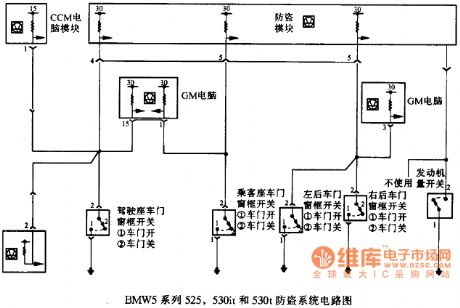
Published:2011/7/19 10:32:00 Author:Nancy | Keyword: BMW5 series, anti-theft system
View full Circuit Diagram | Comments | Reading(590)
Published:2009/7/12 23:54:00 Author:May

Minimizes thermal stresses on lamps and controls when programmed operation is repetitive for large number of cycles. Ujt control circuit provides preheating of lamp by triggering light-activated scr late in each half cycle. Setting of R2 determines minimum lamp current to maintain filament temperature just below visible leveL- Silicon Controlled Rectifier Manual, Third Edition, General Electric Co.1964, p216. (View)
View full Circuit Diagram | Comments | Reading(768)
Published:2009/7/16 12:02:00 Author:Jessie
Pulse width can be varied from 0.1 microsec to 10 millisec in decade ranges by changing timing capacitors. Used in commercial radar range unit and in pulse analyzer.-J. Rogers, Fast-Recovery One-Shot Multi Gives 10:1 Width Control, EEE, 14:4, p 44-45. (View)
View full Circuit Diagram | Comments | Reading(508)
Published:2009/7/12 23:52:00 Author:May
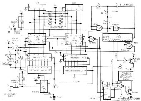
Developed for timing events and for limiting event to predetermined interval that can be set up with 2-digit BCD-encoded thumbwheel switches. Digital display shows time remaining, as guide for speakers. Audible alarm indicates end of time interval. Flashing decimal point indicates counter is working. Designed for operation from two C cells. To conserve power, display is normally blanked; pressing display-enable switch turns on display for about 4 s Article describes operation of circuitin detail,-R.A.Fairman, CMOS Lowers Timer Power Consurnption,EDN Magazine,Oct.5,1975,p78 and 80. (View)
View full Circuit Diagram | Comments | Reading(794)
Published:2009/7/16 11:59:00 Author:Jessie

For applications having only light loading. If required to drive heavy loads, standby efficiency is reduced, and C3 must be so large that circuit could be acidentally turned off by negative supply bus transients.-J. C. Schaeffert and N. F. Goldman, Improved Ultra-Long Monostable Multivibrator, EEE, 12:12, p 57-58. (View)
View full Circuit Diagram | Comments | Reading(553)
Published:2009/7/12 23:51:00 Author:May
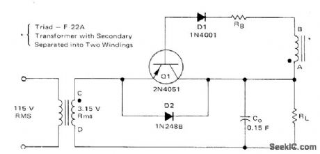
Transistoral is synchronously biased on by AC input voltage to give efficient low-voltage regulation. When points A and C are positive with respect to points B and D, base-emitter junction of Q1 is forward-biased and collector current flows through load RL. On negative alternations,Q1 is reverse-biased and transistor is blocked.-B. C. Shiner, Improving the Efficiency of Low Voltage, High-Current Rectification, Motorola, Phoenix, AZ, 1973, AN-517, p 3. (View)
View full Circuit Diagram | Comments | Reading(836)
Published:2011/7/19 10:34:00 Author:Nancy | Keyword: anti-theft system, BMW5 series
View full Circuit Diagram | Comments | Reading(409)
| Pages:730/2234 At 20721722723724725726727728729730731732733734735736737738739740Under 20 |
Response in 12 hours
© 2008-2012 SeekIC.com Corp.All Rights Reserved.