
Circuit Diagram
Index 739
FOUR_DIGIT_COUNTER
Published:2009/7/12 23:14:00 Author:May
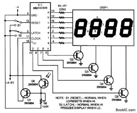
A general-purpose four-digit counter can be made from a 74C925 IC and a few external components. That IC contains the counter, multiplexer, and seven-segment digit drivers, all in one convenient package. A couple of important notes about the circuit: The seven 220-Ω resistors (R1 to R7) are used as dropping resistors between the driver outputs and the segments of the display to protect the LEDs and keep the 74C925 from overheating. The four 2N3904 transistors (Q2 to Q5) act as amplifiers for the digital drivers to keep the display at full illumination. Switches S1 and 52, for reset and latch, respectively, are not crucial, but are highly recommended. The latch will freeze the count if needed. If the switches are not used, pin 12 needs to go to ground, and pin 5 to +V (the circuit's voltage supply). If more than four digits are needed, use the MM74C9261C. The functions are the same, but it has a carry out to cascade more than one chip and four-digit display. (View)
View full Circuit Diagram | Comments | Reading(7606)
AMPLITUDE_DISCRIMINATOR
Published:2009/7/16 21:08:00 Author:Jessie

Used in nuclear physics to determine whether voltage or current input pulse is above or below predetermined level. Triggering threshold is set by adjusting bias of diode D1. Accuracy is within 1 microamp at 50-microamp triggering level, or within 0.4 mv at 10-my triggering level-F. S. Goulding and L. B. Robinson, Achieving Discriminator Levels with a Biased Input Diode, Electronics, 33:21, p 89-91. (View)
View full Circuit Diagram | Comments | Reading(0)
10_GHz_WAVEMETER_AMPLIFIER
Published:2009/7/12 23:12:00 Author:May
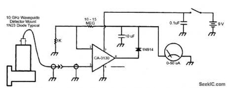
This wavemeter amplifier is connected to the microwave waveguide detector. This circuit operates from a single 9-V transistor radio battery for simplicity.
(View)
View full Circuit Diagram | Comments | Reading(1476)
NEGATIVE_REGULATOR
Published:2009/7/16 21:07:00 Author:Jessie

Regulating negative voltages with minimal dropout is now possible with the LT1185 universal voltage regulator. It supplies up to 3 A of output current with a dropout voltage guaranteed to be less than 1.2 V. The five-lead TO-220 package includes a pin that allows accurate current-limit adjustment for lower-current applications. Although aimed primarily at negative regulation applications, the LT1185 works equally well as a floating positive regulator. Output voltage is programmable from 2.3 to 30 V. (View)
View full Circuit Diagram | Comments | Reading(1060)
12_V_TO_6_V
Published:2009/7/12 23:12:00 Author:May
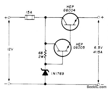
Permits operation of older 6-V VHF FM mobile equipment from 12-V storage battery. With transistor mounted on suitable heatsink, maximum output is 15 A. If positive and negative lines are isolated from chassis, converter may be used with either negative or positive ground.-E. Noll, Circuits and Techniques, Ham Radio, April 1976, p 40-43. (View)
View full Circuit Diagram | Comments | Reading(733)
14_V_AT_250mA_FOR_CASSETTE_DECK
Published:2009/7/16 21:07:00 Author:Jessie

Used in high-quality stereo cassette deck operating from AC line or battery. For U.S. applications, use 120-V power transformer. Power for cassette motor is taken directly from power-supply filter capacitors through 20-ohm 10-W resistor, with negative return line connecting directly to filter capacitors instead of chassis, to eliminate noise originating from pulsating current of cassette-drive motor-control circuit. Article gives all other circuits of cassette deck and describes operation in detail.-J. L. Linsley Hood, Low-Noise, Low-cost Cassette Deck, Wireless World, Part 2 - June 1976, p 62-66 (Part1 - May 1976, p 36-40;Part 3 – Aug. 1976,p 55-56). (View)
View full Circuit Diagram | Comments | Reading(1709)
FAlL_SAFE_TIMER_FOR_TRAlNS
Published:2009/7/12 23:12:00 Author:May
Provides delays up to 4 min, adiustable in 2-s steps, with accuracy better than 5%. Patented circuit was developed by ML Engineering to provide appropriate automatic braking or other action if engineer on train fails to respond to signal within period of delay.-W.E. Anderton,Computers,Communication and High Speed Railways,Wireless World, Aug,1975,p 348-353. (View)
View full Circuit Diagram | Comments | Reading(698)
UHF_SYNCHRONIZER
Published:2009/7/16 21:06:00 Author:Jessie

Simple tunnel-diode circuit can synchronize any scope to any constant frequency up to signal-bondwidth limits of scope, even though bandwidths are greater than cro sync circuits can handle. Upper frequency limit of circuit is at least 1.2 gc. Diode oscillates at frequency controlled primarily by L1, but will lock onto uhf input signal and deliver exact subharmonic of input. Can provide countdowns at ratios exceeding 100:1.-F.M. Carlson,Tunnel- Diodo UHF Synchronizer, EEE, 12:2, p 109. (View)
View full Circuit Diagram | Comments | Reading(616)
Long time timing circuit formed by the LM106
Published:2011/7/27 9:49:00 Author:Nancy | Keyword: Long time timing circuit
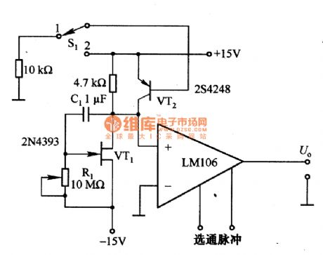
Figure 1 is the long time timing circuit formed by the LM106. The circuit is VT1 (FET tube) mueller integral circuit, if the gain of the circuit is A, the timing constant can be increased to A times. The gain of VT1 is about 60, the equivalent capacitance converted to VT1 grid is increased to 60 times, namely, 60 C1 is equal to 60 μF, and the maximum value of the grid resistance R1 is lOMΩ, so the timing can reach 6005. S1 is a reset switch, it resets when connects to 1 and VT2 conducts, C1 discharges through VT2 and resets to prepare timing for the next time. LM106 is a comparator circuit, the output is connected to corresponding circuit and for timing control. (View)
View full Circuit Diagram | Comments | Reading(583)
10_min_WITH_BLINKING
Published:2009/7/12 23:10:00 Author:May
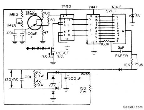
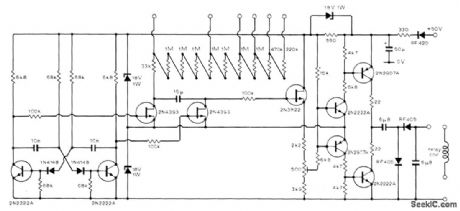
Station-identification timer uses single Nixie display to indicate elapsed time in minutes. After 9 min, numeral 9 blinks for 60 s before resetting to zero as visual reminder that amateur radio station identification should be made. Transistor can be GE X10 or 2N2646, Diodes are 1N4001 or equivalent. Numeral 9 or Nixie is connected as relaxation oscillator, flash rate of which can be changed by changing value of 100K resistor connected to pin 9.-W. Pinner, ID Timer, 73Magazine, Aug.1974, p 95-96.
(View)
View full Circuit Diagram | Comments | Reading(707)
DC_TO_DC_CONVERTER_FOR_DIGITAL_PANEL_METERS
Published:2009/7/16 21:06:00 Author:Jessie

Often a digital panel meter is used in an application where the meter is on the hot side of a Circuit This supply will provide the 9-to 12-Vdc floating supply for the meter. (View)
View full Circuit Diagram | Comments | Reading(1403)
DUMMY_LOAD_AND_DETECTOR
Published:2009/7/12 23:08:00 Author:May

Two 100-Ω, 1/2-W resistors in parallel connected across a 50-Ω cable with near-zero lead lengths will be very close to a 50-Ω termination with the SWR less than 1.1:1. However, adding the diode introduces capacitor loading that results in an SWR of 1.5:1 or more. In the circuit, the components on the 2-dB resistor pad preceding the diode/load compensate for this, as they are tailored to reduce the SWR to less than 1.1: 1. Although the power capability of this assembly is 5 W, forced-air cooling is required at the higher power levels, depending on the measurement period.Schematic and layout of the dummy-load/detector assembly: A. Input, 1 ft RG-58/U. Fan out braid on connectink end, twist in two segments, and solder to PC board with minimum lead lengths. B. Base, 3 in2 ×in×1/16 in PCB. C. Capacitor-90° circular sector, 1 in radius, 0.21-in-thick Reynolds sheet aluminum. Surface polish with 220-grit sandpaper to remove burrs. Dielectric, 2.7-mil polyethylene (Ziploc heavy-duty freezer bag). Feed through 2-56 screw with a plastic insulator on the back side. Hole is reamed on both sides with a large drill to prevent shorting to the foil. D. Peak readout diode, 1N34A selected to have a reserve resistance of less than 5 MΩ (RS 276-1123). E. Component tie-down pads, 1/4 in1/×8 in×1/16 in glass-epoxy PC board. Cemented to base with clear household cement (Elmer's). F. Output tie-down pad 3/8 in1×/4 in×1/16 in PC board. (View)
View full Circuit Diagram | Comments | Reading(947)
RASTER_VERTICAL_TRIGGERING_GENERATOR
Published:2009/7/16 21:06:00 Author:Jessie

Output pulse width of blocking oscillator Q1 is over 3.5 microsec, determined by T1 and C2.Q2 couples this pulse to output H for use as unsynchronized output, while 03 with 400-kc sync input serves with D2 as coincidence gate to give output only when both sync and gate pulses are present-R. P. Ruler and W. A. Karlotski, Use Raster Oscilloscopes for Faster Time Measurements, Electronics, 35:52, p 38-42. (View)
View full Circuit Diagram | Comments | Reading(660)
EVENT_REGISTER
Published:2009/7/12 23:08:00 Author:May
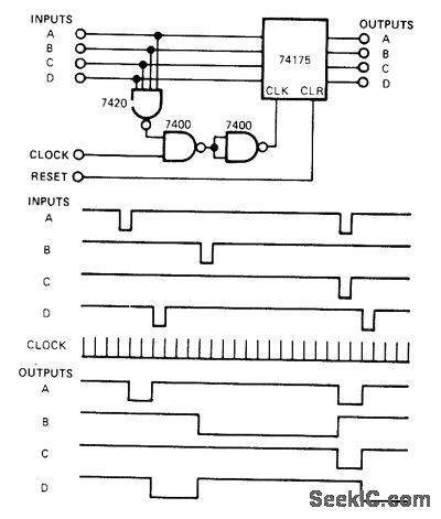
Inputs from sequential timer provide pulsed output and operate de-vices which stay on until next timed event. When an input goes low, output of four-input positive-NAND 7420 goes high, enabling the clock for 74175 4-bit D-type register. Since event-timer clock signal is used, outputs of register are coincident with clock. All outputs remain until one or more inputs goes low.-J. Glaab, Time Events with a Pulse Output Contrailer, EDNMagazine, Jan. 5, 1977, p 43. (View)
View full Circuit Diagram | Comments | Reading(1232)
25_A_125_to_25_V_REGULATED_POWER_SUPPLY
Published:2009/7/16 21:05:00 Author:Jessie

This power supply uses an LM317J adjustable regulator and an MJ2955 pass transistor, Q1 and U2 as well as U1 should be heatsinked. A suitable heatsink would typically be 4 x4 x 1 fins, extruded type, because up to 65 W dissipation can occur. R8 and R9 should be 1% types or selected from 5% film types with an accurate ohmmeter. Capacitors are disc ceramic except for those with polarity marked, which are electrolytic. (View)
View full Circuit Diagram | Comments | Reading(1697)
SEQUENTIAL_TIMER_1
Published:2009/7/12 23:07:00 Author:May

Second Exar XR-2242 long-range timer is triggered when first timer completes its cycle, length of which is equal to 128R1C1. Output of second timerthus stays high for T1 = 128R1C1 after trigger is applied, then goes low for duration T2 =128R2C2 corresponding to timing interval of unit 2. Circuit then reverts to rest state.- Timer Data Book, Exar Integrated Systems, Sunnyvale, CA, 1978, p 19-22. (View)
View full Circuit Diagram | Comments | Reading(0)
35_V_7_A_LINEAR_REGULATOR_SUPPLY
Published:2009/7/16 21:05:00 Author:Jessie

The LT1580 linear regulator circuit shown achieves ±2 percent dc output-voltage accuracy at up to 7 A load current. This circuit restricts the output-voltage transients because of 200-mA to 4-A load-current steps to 65 mV p-p. The LT1580 has a separate remote sense input that maintains the dc voltage at the load accurately, independent of the load current. Output-voltage variation over the full load-current range, known as Load regulation, with remote sense connected (R3 = 0Ω) is very close to ±0 percent. The LT1580 transient response to 3.8-A-load current steps is 88.7 mV p-p (R3 = 0Ω). Resistor R3 is added to intentionally introduce some dc load regulation. The feedback resistors are chosen to set the no-load output voltage slightly higher than 3.5 V. At 4-A load current, the output voltage is regulated slightly below 3.5 V. (View)
View full Circuit Diagram | Comments | Reading(677)
15V_AT_1_A
Published:2009/7/16 21:05:00 Author:Jessie

Developed for operating CRO from AC line. Can also be used for recharging batteries of portable CRO if pot is set to correct charging voltage for cells being used. Use good heat-sink with 7812 regulator.-G. E. Friton, Eyes for Your Shack, 73 Magazine, Jan.1976, p 66-69.
(View)
View full Circuit Diagram | Comments | Reading(1686)
REPEATER_EMERGENCT_POWER_SUPPLY
Published:2009/7/12 23:06:00 Author:May

If your repeater needs emergency power, this circuit might do. Connect a 12-V storage battery, a relay, and a 0.5-Ω 50-W resistor as shown. Normally, the battery charges at a low rate (less than 1 A) through the 0.5-Ω resistor. When power fails, current can flow from the battery through the diode for a few milliseconds, until the relay drops out and closes the contacts, completely eliminating any voltage drop. If your repeater doesn't use a 13.8-V power supply, you could purchase a 2-A battery charger and connect a 0.5- to l-Ω resistor (50 W) in series with the battery. This will charge at approximately 1/2 A and maintain the battery. (View)
View full Circuit Diagram | Comments | Reading(760)
WWV_TO_75_m_BAND_CONVERTER
Published:2009/7/12 23:04:00 Author:May
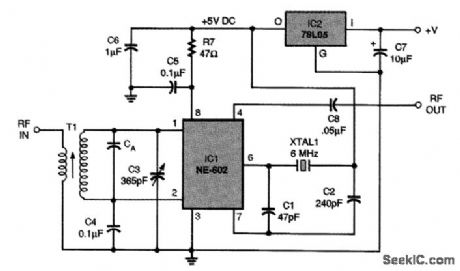
This circuit for an HP-band converter will convert the 10-MHz WWW signal to a frequency in the 75-m ham band. The local oscillator section of NE-602 is available on pins 6 (base) and 7 (emitter). In this circuit, a 6.00-MHz crystal oscillator is provided by the NE-602. Capacitors C1 and C2 form the feedback network. The junction of C2 and XTAL1 can be connected to either the 15-Vdc line or ground (the former is shown here). The difference frequency between WWV's 10 MHz and the 6.00-MHz crystal frequency is 4.00 MHz, which is located at the top end of the 75-m ham band. Crystals with other frequencies will produce other output sum or difference frequencies, so tune the receiver appropriately if something other than 6.00 MHz is used. (View)
View full Circuit Diagram | Comments | Reading(1337)
| Pages:739/2234 At 20721722723724725726727728729730731732733734735736737738739740Under 20 |
Circuit Categories
power supply circuit
Amplifier Circuit
Basic Circuit
LED and Light Circuit
Sensor Circuit
Signal Processing
Electrical Equipment Circuit
Control Circuit
Remote Control Circuit
A/D-D/A Converter Circuit
Audio Circuit
Measuring and Test Circuit
Communication Circuit
Computer-Related Circuit
555 Circuit
Automotive Circuit
Repairing Circuit