
Circuit Diagram
Index 734
The 0TL power amplifier connection circuit diagram of Ordinary power tube changing into triode
Published:2011/8/3 22:30:00 Author:Ecco | Keyword: 0TL , power amplifier connection , Ordinary power tube , triode

View full Circuit Diagram | Comments | Reading(1038)
SENSING_CANE_FOR_BLIND
Published:2009/7/16 6:05:00 Author:Jessie

Capacitance-sensing probe in tip of cane changes frequency of one oscillator in accordance with distance from ground, curb, or holes, to make beat-frequency oscillator produce audio tone in headset worn by blind person.-J. Markus and V. Zeluff, Handbook of Industrial Electronic Control Circuits, McGraw-Hill, N.Y., 1956, p 24. (View)
View full Circuit Diagram | Comments | Reading(1136)
THREE_COIL_CRYSTAL_RECEIVER
Published:2009/7/12 23:44:00 Author:May

This circuit uses three inductors to increase the receiver's selectivity and sensitivity. Components L2 and C1 are used in an antenna impedance-matching circuit, while L1 and C2 operate in a series-tuned low-output impedance circuit that matches the impedance of the diode detector. A 1-to 2-mH inductor (L3), as in the previous circuit, offers dc continuity to the detector circuit. (View)
View full Circuit Diagram | Comments | Reading(1324)
BALANCED_FOUR_FET_MIXER
Published:2009/7/16 6:04:00 Author:Jessie
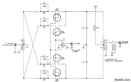
Uses two matched FET pairs to bring third-order inter-modulation distortion suppression down to 71 dB. Developed for use in high-quality communication receiver.-U. L. Rohde, Optimum Design for High-Frequency Communications Receivers, Ham Radio, Oct. 1976, p 10-25. (View)
View full Circuit Diagram | Comments | Reading(1002)
FLIP_FLOP_FOR_DATA_REGISTER
Published:2009/7/16 6:03:00 Author:Jessie

Eccles-Jordon type circuit uses surface-barrier transistors with saturation biasing. Large registers for computers are assembled by using one flip-flop per digit.-W. Orvedahl and J. H. Shepherd, Designing Data Registers with Simple Diode Circuits, Electronics, 36:8, p 48-50. (View)
View full Circuit Diagram | Comments | Reading(669)
BODY_CAPACITANCE_ALARM
Published:2009/7/16 6:03:00 Author:Jessie

Detects intruder by sensing body capacitance. Oscillator Q1 feeds 20 kc to capacitance bridge that contains C1, which is capacitance to ground of protected cabinet. When unbalanced, bridge feeds 20-kc signal to amplifier Q2, whose output goes to phase-sensitive detector D1-D2, which converts unbalance signal into d-c voltage for amplification by Q3. At balance, Q4 and Q5 send about I ma through relay K1 to keep it energized. When intruder approaches protected cabinet, output of phase-sensitive detector becomes more negative, causing K1 to drop out and sound an alarm.-S. M. Bagno, Sensitive Capacitance Intruder Alarm, Electronics, 33:38, p 65-67. (View)
View full Circuit Diagram | Comments | Reading(761)
ANEROID_DRIVEN_CAPACITOR
Published:2009/7/16 6:02:00 Author:Jessie

Datum stabilizer for radar-altimeter surveying uses oscillator to produce output current proportional to change in altitude. Resonant frequency of high-stability 3.5-Mc oscillator is varied by small capacitor plate driven by three-element aneroid. Discriminator and d-c amplifier transform resulting frequency changes to current variations proportional to changes in height.-J. Markus and V. Zeluff, Handbook of Industrial Electronic Control Circuits, McGraw-Hill, N.Y., 1956, p 23.
(View)
View full Circuit Diagram | Comments | Reading(669)
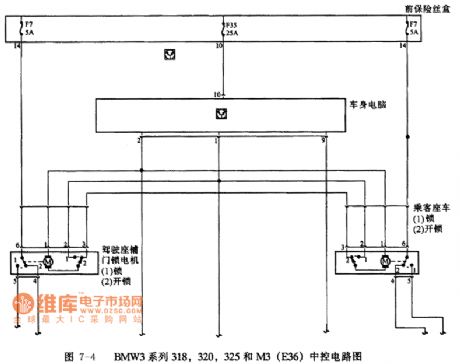
BMW3 series 318,320,325 and M3(E36) anti-theft system circuit 4
Published:2011/7/19 10:41:00 Author:Nancy | Keyword: BMW3 series, anti-theft system
View full Circuit Diagram | Comments | Reading(655)
INTRUSION_ALARM
Published:2009/7/16 6:00:00 Author:Jessie

Circuit stops oscillating when intruder approaches antenna surrounding area being protected. Uses weak oscillator with relay tube that is biased to cutoff by some of oscillator output. Additional capacitance caused by intruder stops oscillator, removing bias and making tube conduct and actuate relay to sound alarm.-J. Markus and V. Zeluft, Handbook of Industrial Electronic Control Circuits, McGraw-Hill, N.Y., 1956, p 19. (View)
View full Circuit Diagram | Comments | Reading(572)
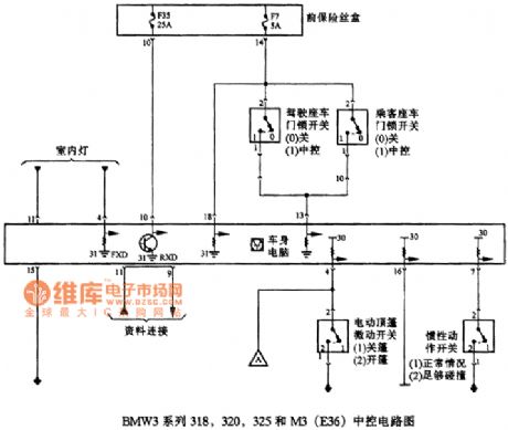
BMW3 series 318,320,325 and M3(E36) central control circuit 2
Published:2011/7/19 10:43:00 Author:Nancy | Keyword: BMW3 series, central control
View full Circuit Diagram | Comments | Reading(475)
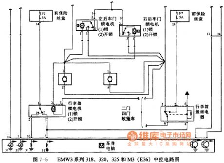
BMW3 series 318,320,325 and M3(E36) central control circuit 1
Published:2011/7/19 10:44:00 Author:Nancy | Keyword: BMW3 series, central control
View full Circuit Diagram | Comments | Reading(347)
PLL_IN_AM_RECEIVER
Published:2009/7/16 5:58:00 Author:Jessie

Phase-locked loops provide required stability for synchronous detection to improve reception quality of commercial double-sideband AM transmissions. Signal input and output of VCO are multiplied in phase-sensitive detector or multiplier that produces voltage proportional to phase difference between input and VCO signals. After filtering and amplifying, this voltage is used to control frequency of VCO to make it synchronize with incoming signal. Features include absence of image responses since IF is 0 Hz, almost complete immunity to selective fading, and conversion of RF to audio at very low signal levels so overall receiver gain is achieved mainly in audio amplifier. Article traces development and operation of receiver in detail.-T. Mollinga, Solve Phase Stability Problem in AM Receivers with PLL Techniques, EDN Magazine, Feb. 20, 1975, p51-56. (View)
View full Circuit Diagram | Comments | Reading(1324)
CAPACITANCE_TRANSDUCER_FOR_30000_RPM_IACHOMETER
Published:2009/7/16 5:57:00 Author:Jessie

R-f oscillator is adjusted to oscillator feebly anywhere between 500 and 2,000 kc. When pickup capacitance increases, it shunts oscillator feedback circuit more, reducing its r-f output voltage. Resulting drop in a-c component of rectified r-f carrier is amplified to drive tachometer or frequency meter. Pickup is mounted close to moving blades on shaft whose speed is being measured.-J. Markus and V. Zeluff, Handbook of Industrial Electronic Control Circuits, McGraw-Hill, N.Y., 1956, p 17. (View)
View full Circuit Diagram | Comments | Reading(574)
MONITORING_ENAMEL_THICKNESS_ON_WIRE
Published:2009/7/16 5:55:00 Author:Jessie

Wire is run through mercury-filled vessel. Bridge output goes to pair of mixer tubes (6AJ8 is U.S. equivalent) whose plate circuits form d-c vtvm, with milliammeter indicating amount of bridge unbalance. Bridge is formed by connecting mercury vessel, grounded wire, fixed capacitor, and variable capacitor to secondary coil of differential transformer.-Monitor Wire Enamel by Capacitance Bridge, Electronics, 33:44, p 92-97. (View)
View full Circuit Diagram | Comments | Reading(596)
CONTROLLING_EXTRUSION_OF_PLASTIC_ON_WIRE
Published:2009/7/16 5:54:00 Author:Jessie

Uses sensing probe as one arm of capacitance bridge that is normally balanced with respect to 10-kc phase-shift oscillator signal. Oscillator output is compared with bridge unbalance in mixer that determines directional error. Output of mixer is amplified to control servo-driven rheostat which in turn controls speed at which wire is pulled, to hold capacitance within desired limits. Sensing electrode is water trough, with water in contact with extruded insulation to form one side of unknown capacitor. Wire is grounded to form other side.-J. Markus and V. Zeluff, Handbook of Industrial Electronic Control Circuits, McGraw-Hill, N.Y., 1956, p 18. (View)
View full Circuit Diagram | Comments | Reading(648)
DIRECT_CONVERSION_PRODUCT_DETECTOR
Published:2009/7/16 5:53:00 Author:Jessie

Antenna is matched to high-impedance gate input of JFET with resonant input transformer. Demodulating carrier is applied to same gate. RC filter and audio transformer in output circuit of JFET recover demodulating audio while filtering out RF signals and undesired mixing components.-E. M. Noll, FET Principles, Experiments, and Projects, Howard W. Sams, Indianapolis, IN, 2nd Ed., 1975, p 155. (View)
View full Circuit Diagram | Comments | Reading(2020)
PLATE_TO_GRID_COUPLED_MAIN_GATE_MVBR_
Published:2009/7/16 5:53:00 Author:Jessie

Used in combination search and gun-laying radar. Triggered by connecting plate of trigger inverter or switch tube in parallel with plate of normally-off mvbr tube. Provides positive unblanking gate for crt. Different gate lengths are obtained by switching mvbr capacitors.-NBS, Handbook Preferred Circuits Navy Aeronautical Electronic Equipment, Vol. 1, Electron Tube Circuits, 1963, p N10-2. (View)
View full Circuit Diagram | Comments | Reading(901)
BALANCED_CAPACITANCE_FENCE_ALARM
Published:2009/7/16 5:53:00 Author:Jessie

Sets off alarm when anyone approaches barbed wire fence around power plant or substation. Automatically corrects for capacitance changes due to weed growth and changing weather conditions. Two separate antennas and two oscillators are used, with lines along fence serving as part of tuning capacitance of each oscillator. Mixer produces beats between harmonics. Frequency-selective network in low a-f range produces d-c voltages that trigger relay tubes and actuate alarm relays. – J. Markus, Handbook of Electronic Control Circuits, McGraw-Hill, N.Y., 1959, p 1. (View)
View full Circuit Diagram | Comments | Reading(1753)
PROXIMITY_SWITCH
Published:2009/7/16 5:50:00 Author:Jessie

Sensor plate and C2 form capacitive voltage divider across a-c supply. Value of C2 depends on proximity to sensor plate of human body, grounded object, or other reasonably conductive object. When voltage across C1 exceeds breakdown of neon, C1 and C2 discharge through scr gate, causing scr to trigger and energize load. Latching action is obtained by driving scr an ode circuit with d-c, for such applications as elevator floor selector buttons and door safety controls.- Silicon Controlled Rectifier Manual, Third Edition, General Electric Co., 1964, p 122. (View)
View full Circuit Diagram | Comments | Reading(3022)
CASCADED_ONE_SHOTS_GENERATE_PULSES_IN_BURST
Published:2009/7/16 5:50:00 Author:Jessie

Addition of redundant stages to timing portion of conventional monostable mvbr permits generating bursts of eleven 2-kc pulses every 0.1 sec. Used for testing decimal counters at high counting rotes; each burst gives visible one-digit advance in readout because of 94.5-millisec time between bursts.-J. Gaon, Simple Counter Tester Uses Cascaded One-Shots, Electronics, 36:14, p 40-41. (View)
View full Circuit Diagram | Comments | Reading(575)
| Pages:734/2234 At 20721722723724725726727728729730731732733734735736737738739740Under 20 |
Circuit Categories
power supply circuit
Amplifier Circuit
Basic Circuit
LED and Light Circuit
Sensor Circuit
Signal Processing
Electrical Equipment Circuit
Control Circuit
Remote Control Circuit
A/D-D/A Converter Circuit
Audio Circuit
Measuring and Test Circuit
Communication Circuit
Computer-Related Circuit
555 Circuit
Automotive Circuit
Repairing Circuit