
Circuit Diagram
Index 735
TUNABLE_DUAL_COIL_CRYSTAL_RADIO
Published:2009/7/12 23:43:00 Author:May

The 12-turn primary winding couples the RF signal from the antenna/ground system to the 48 turn secondary winding. Here C1, a 365-pF variable capacitor, tunes the L/C circuit to the desired radio-frequency signal. A 1N34A germanium diode, D1, detects the audio and feeds it to the headphones (Z1). The various taps on L1's secondary allow impedance matching of the antenna/ground system and the detector diode, as well as the inductance value needed to tune to the desired RF signal. (View)
View full Circuit Diagram | Comments | Reading(1898)
1_h_HOUSEHOLD_TIMER
Published:2009/7/12 23:43:00 Author:May

NE555 timer circuit turns off television set or other device at any desired time up to about 1 h after start switch is closed. Use IRC MR312C relay having coil resistance of 212 ohms, or other 12-V relay drawing less than 200 mA. With values shown, R2 gives time delay range of 3 to 58 min. For other ranges, change values of R2 and C1. Clockwise from top, pins on NE555 are 8,3, 4, 2, 1, 7, and 6.-P. C. Walton, Build This $5 Timer, 73 Magazine, Jan. 1976, p 129. (View)
View full Circuit Diagram | Comments | Reading(1019)
2_W_STEREO_AMPLIFIER
Published:2009/7/12 23:42:00 Author:May

The amplifier is built around a ULN2274B dual audio power amplifier and provides a maxintum of 2 W of quality sound. Because the amplifier is composed of two identical subcircuits, only one subcircuit will be covered. Resistor R5 sets the tone and it can be replaced with a variable unit; lower values of that resistor produce more bass. The bias is set by R6 and C4, and R7, R9, and C5 are feedback elements. For a more realistic sound, R8 and C3 are used to roll off the high frequencies. Capacitor C6 is a dc-blocking capacitor. The circuit chip requires from 6 to 26 Vdc without distortion.
(View)
View full Circuit Diagram | Comments | Reading(833)
FULL_WAVE_DETECTOR_ORYSTAL_SET
Published:2009/7/12 23:42:00 Author:May

The 12-turn coil of L1 couples the RF signal to the large coil, L2. Connect the center tap of L2 to ground, the fourth tap up from the center to diode D1, and the fourth tap down from the center to diode D2. The combined audio output drives the headphones (Z1), If you change tap positions, keep the same number of turns on each side of center. That will balance the RF that feeds each detector diode. The circuit's sensitivity and audio output can be increased by placing L1 inside of L2 (the forms specified for the coils should make that possible). For maximum selectivity, L1 should be loose-coupled to L2. (View)
View full Circuit Diagram | Comments | Reading(1158)
PROGRAM_TIMER
Published:2009/7/12 23:41:00 Author:May

Measures time between two points in microprocessor program while program is running. Gated 1-MHz crystal oscillator feeds Fluke 1941A counter used in totalize mode. Gate input is connected to unused bit of output port on microprocessor system. Instruetions are then inserted in program under test to gate counter on at beginning of desired step and turn it off at end. I)isplay then shows number of microseconds required by microprocessor to execute instructions.-M. M. Dodd, Benchmark Timer Eliminates Need to Total Individual Execution Times, EDNMagazine, Oct.20,1975,p91-92. (View)
View full Circuit Diagram | Comments | Reading(979)
SIMPLE_GUITAR_AMPLIFIER_WITH_DUAL_INPUTS
Published:2009/7/12 23:40:00 Author:May

This amplifier uses an LM386 IC and has two inputs, an input for guitar and a separate audio input for a second guitar, a mike, etc. Power is supplied by a 9-V battery. While headphones are indicated, the amplifier will drive a small speaker. Output is around 300 to 500 mW, depending on load and battery voltage.
(View)
View full Circuit Diagram | Comments | Reading(4319)
SIMPLE_AUDIO_OUTPUT_AMPLIFIER
Published:2009/7/12 23:39:00 Author:May

This audio amplifier circuit has a gain of about 20. A supply of 3 to 12 V cart be used. Output is up to about 1 W, depending on load impedance and supply voltage. (View)
View full Circuit Diagram | Comments | Reading(782)
130_AND_270_V_FOR_CRT
Published:2009/7/12 23:39:00 Author:May

High-voltage power supply provides 270 V required for deflection plates of 2AP1-A CRT used as RTTY tuning indicator, as well as 130 V for high-voltage amplifier. Large capacitor keeps ripple voltage low.-R. R. Parry, RTfY CRT Tuning Indicator, 73 Magazine, Sept. 1977, p 118-120. (View)
View full Circuit Diagram | Comments | Reading(787)
MINIATURE_AUDIO_POWER_AMPLIFIER
Published:2009/7/12 23:38:00 Author:May
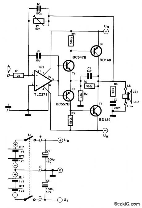
A compact audio poirer amplifier with low current drain has many applications. These are the design basis for the mini amplifier. It continues working satisfactorily with a battery voltage down to 1.5 V. Its quiescent current drain is about 1 mA, and its efficiency is a worthwhile 70 percent. It provides an output power of 500 mW into 8 Ω (or 800 mW into 4 Ω), has a sensitivity of 400 mV, and its distortion is never higher than 1.2 percent. Because the output transistors have no emitter resistor, the voltage is determined solely by the knee voltage of T3 and T4. With a load of 4 to 8 Ω, these voltages are limited to 0.2 to 0.3 V so that the transistors can be driven virtually up to the supply voltage. The overall bandwidth of the amplifier is limited to not less than 21 kHz at the maximum amplification of x5. With a 4-Ωload, the peak output current is 700 mA. A 315-mA fuse in series with the output is, therefore, a simple but effective short-circuit protection. At maximum drive with a music signal, the average current is only 50 mA. In operation the drive will never be continuously maximum, so the actual current drain will be much lower. A set of four penlight batteries should last about 200 hours.
(View)
View full Circuit Diagram | Comments | Reading(2010)
STEREO_PREAMP
Published:2009/7/12 23:35:00 Author:May
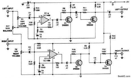
The output of the audio source is fed to the left and right inputs of the circuit (J1 and J2). Potentiometers R1 and R2 control the volumes of the input signals, while potentiometer R17 is a balance control. The incoming signals are coupled through capacitors C1 and C2 to the noninverting inputs of op amps IC1-a and IC1-b. Because IC1 operates as a single-supply amplifier, its output signal fluctuates above and below half of the supply voltage. The output signals of the op amps are coupled to the bases of two 2N2222 transistors (Q1 and Q2), which further amplify the left and right signals. Then, the outputs of the transistors are coupled to the bases of two more 2N2222 transistors (Q3 and Q4), further boosting the left and right signals. The transistor pairs also act as buffers.
(View)
View full Circuit Diagram | Comments | Reading(1654)
12_V_EMERGENCY_POWER
Published:2009/7/12 23:35:00 Author:May

Trickle-charge circuit and 12-V motorcycle battery provide reliable emergency power for battery-operated weather radio, fiortable AM/FM receiver, or hand-held transceiver for many hours. 100K pots drop voltage to 9 V for each receiver. Lamp can be auto dome light. GE-63 pilot lamp in charging circuit acts as current limiter and charge indicator.-J. Rice, Simple Emergency Power, QST, March 1978, p 42. (View)
View full Circuit Diagram | Comments | Reading(1386)
LONG_INTERVALS_WITH_SMALLC
Published:2009/7/12 23:35:00 Author:May

Use oftwo CA3098 dual-input precision level detectorseliminates need for expensive high-capacitance low-leakage timing capacitors when delay intervals of several hours are required. For 4-h timer, CT is only 16 μF if Rc is 22 megohms and RD is 100 kilohms. Article traces circuit operation and gives design equations.-G. J. Granierl,Precision Level Detector IC Simplifies control Circuit Design,EDN Magazine, Oct 5,1975,p 69-72. (View)
View full Circuit Diagram | Comments | Reading(1178)
NEON_CRT_BIAS_REGULATOR
Published:2009/7/16 21:23:00 Author:Jessie

Neon lamp serves as bias regulator for grid 1 of oscilloscope crt and as pilot lamp.-More Glow-Lamp Circuits, EEE, 12:2, p 106-108. (View)
View full Circuit Diagram | Comments | Reading(880)
POWER_BUFFER_BOOSTS_REFERENCE_CURRENT
Published:2009/7/16 21:24:00 Author:Jessie

A method of boosting the output current of a reference and also protecting against overloads is shown in Fig. 66-5. IC1 acts as a power buffer. The LT1027 forces the output of VOUT and ground to be 5 V. The RC damper (50Ω and 0.1 μF) provides loop stability. The output might oscillate if low ESR capacitors are connected to it, so use aluminum electrolytic or tantalum capacitors instead of ceramic or mylar. (View)
View full Circuit Diagram | Comments | Reading(870)
EFFICIENT_REGULATED_STEP_UP_CONVERTER
Published:2009/7/16 21:24:00 Author:Jessie

Two eight-pin ICs form a regulator circuit that can convert a lithium battery's 3-V output to 5 V and deliver load currents as high as 100 mA. It operates without inductors or transformers, and draws only 200 μA of quiescent current. At Vin = 3 V, it offers 81-percent efficiency with a 100-mA load and 84 percent with a 20-mA load. Efficiency will increase as Vin falls. For example, at Vin = 2.7 V (the cell's loaded output for most of its operating life), efficiency for a 40-mA load current is 90 percent. Voltage from the lithium battery (a 2/3-A size Duracell DS123A) is doubled by the high-current charge pump (IC1). The Schottky diode (D1) is included to assure startup in this configuration.D1 won't affect efficiency because it doesn't conduct load current during normal operation. IC2 is a linear regulator with a dropout voltage of only 40 mV at Iload 40 mA. This load, allowed to drain the battery until Vout = 4.5 V, yields a battery life of 16 hours. Reducing the load to 20 mA extends the battery life to 36 hours. (View)
View full Circuit Diagram | Comments | Reading(892)
Z_AXIS_AMPLIFIER
Published:2009/7/16 21:24:00 Author:Jessie
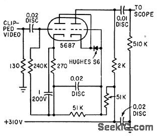
Accepts dipped video signal of microwave interferometer system and intensity-modulates electron beam of oscilloscope.-H. L. Bunn, Determining Electron Density and Distribution in Plasmas, Electronics, 34:14, p 71-75. (View)
View full Circuit Diagram | Comments | Reading(742)
CONSTANT_CURRENT_TEST_LOAD
Published:2009/7/16 21:23:00 Author:Jessie

This circuit will supply a constant load of 500 mA to 1.5A. R4 controls the current while R3 provides fine adjustment. (View)
View full Circuit Diagram | Comments | Reading(1298)
Z_AXIS_MODULATION
Published:2009/7/16 21:22:00 Author:Jessie

Pulse amplifier allows crt beam-intensity modulation from 3.v logic levels.Requires only single -150 v supply. Intended as modification for Tektronix oscilloscope.-J. H.Cormack, Pulse Amplifier for Beam Intensity Modulation, EEE, 14:1, p 63. (View)
View full Circuit Diagram | Comments | Reading(865)
BACKUP_SUPPLY_ACTIVATES_BY_DROP_IN_MAIN_SUPPIJY
Published:2009/7/16 21:22:00 Author:Jessie

A supply monitor using two TL7702A chips monitors the ±15-V supplies and activates the backup supply in case of a voltage drop. Although the chips are intended for use as reset controllers in microprocessor systems, they work well in this application. (View)
View full Circuit Diagram | Comments | Reading(812)
±6_AND_±15_V
Published:2009/7/16 21:22:00 Author:Jessie

Developed for use with function generator. Mount regulators on heatsinks insulated from chassis by mica wafers. Article covers construction and adjustment to give exactly desired outputs.-H. Olson, Build This Amazing Function Generator, 73 Magazine, Aug. 1975, p 121-124. (View)
View full Circuit Diagram | Comments | Reading(877)
| Pages:735/2234 At 20721722723724725726727728729730731732733734735736737738739740Under 20 |
Circuit Categories
power supply circuit
Amplifier Circuit
Basic Circuit
LED and Light Circuit
Sensor Circuit
Signal Processing
Electrical Equipment Circuit
Control Circuit
Remote Control Circuit
A/D-D/A Converter Circuit
Audio Circuit
Measuring and Test Circuit
Communication Circuit
Computer-Related Circuit
555 Circuit
Automotive Circuit
Repairing Circuit