
Circuit Diagram
Index 728
State variable oscillation circuit diagram
Published:2011/8/4 1:53:00 Author:Ecco | Keyword: State variable oscillation

Op amps A1, A2 and A3 are the basic circuits, and M1. , M2, M3 and M4 use the shock stabilizing circuit, but can also use other forms of circuits. The VCA uses the analog multiplier, which is simple with low distortion.
(View)
View full Circuit Diagram | Comments | Reading(933)
STRETCHING_FAST_PULSES_BY_SAMPLING
Published:2009/7/16 20:43:00 Author:Jessie


Attachment for conventional scope samples instantaneous amplitude of signals at different instants of time and reconstructs original shape by peak-detecting amplified and stretched samples. Permits resolving pulse rise times as short as 1/3nanosecond with repetition rates up to 50 kc.-J.J. Amodei, Converting Oscilloscopes for Fast Rise Time Sampling,Electronics,33:26,p 96-99. (View)
View full Circuit Diagram | Comments | Reading(807)
FILM_BREAK_DETECTOR
Published:2009/7/13 1:37:00 Author:May
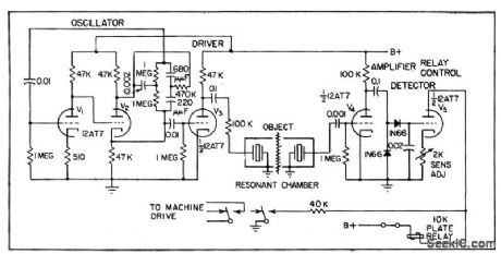
Photographic film in processor is run through resonant acoustic chamber in which presence of film affects en energy transfer between crystal transducers.Change in transducer output when film breaks is used to operate relay through amplifier and detector, to control automatic film processor and thereby minimize rethreading and film spoilage. Can also be used to detect bubbles in rubber tubing during blood transfusions, and detect similar changes in other films, liquids, and gases.-E. L. WIthey and R. G. Seed, Acoustic Cavity Detects Breaks in Film, Electronics,31:13,p50-51. (View)
View full Circuit Diagram | Comments | Reading(809)
DIODE_MATCHING_CIRCUIT_II
Published:2009/7/16 20:43:00 Author:Jessie


To match diode pairs with this circuit, simply insert diodes of equal rating in the D1 and D2 positions. When the DVM reading drops to zero or nearly zero, you have found a set. D1 and D2 are diodes under test. S1-a and S1-b select currents of 8 mA, 800μA, or 250μA. (View)
View full Circuit Diagram | Comments | Reading(799)
AUDIO_POWER_BOOSTER
Published:2009/7/13 1:37:00 Author:May

The audio power booster is based on two TDA2006 audio IC power amplifiers. Power amplifier IC1 is used as what is virtually a noninverting amplifier, with the noninverting input of the device beirtg biased to half the supply voltage by R2 and R3. R5 provides 100-percent negative feedback from the output to the inverting input of IC1 at dc so that the circuit has unity voltage gain and the output is biased to the required level of half the supply voltage. C2 and R4 remove some of the feedback at audio frequencies, and this gives a voltage gain of about 18 times at these frequencies. R1 is used at the input of the amplifier to reduce the sensitivity to a more suitable level, and C1 simply provides dc blocking at the input. IC2 is used in virtually the same configuration, but its noninverting input is not fed with an audio signal and it only receives the dc bias signal from R9 and R10. Resistor R11 couples the output signal of IC1 to the invertinginput of IC2, and the value of R11 is chosen to give IC2 an effective voltage gain of unity. However, as the input signal is coupled to IC2's inverting input, there is a phase inversion through this section of the amplifier, giving the required antiphase relationship at the two outputs. Diodes D1 to D4 are protection diodes for the two ICs, while R6 plus C4 helps to prevent instability. Components C3, C5, and C7 are all supply decoupling capacitors. (View)
View full Circuit Diagram | Comments | Reading(2582)
DIODE_MATCHING_CIRCUIT_I
Published:2009/7/16 20:41:00 Author:Jessie
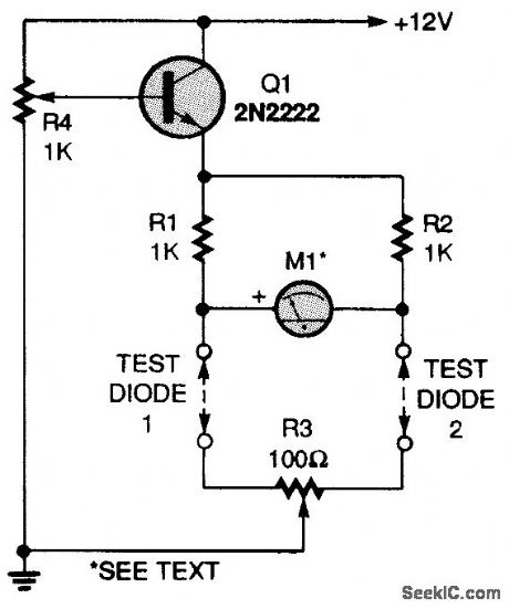
A 2N2222 transistor is connected in an emitter-follower circuit that is powered by a 12-Vdc source. Potentiometer R4 sets the voltage feeding the diodes under test. Two 1000-0,1percent resistors, RI and R2, make up two legs of a four-element bridge circuit. The diodes you want to test make up the other two legs. Potentiometer R3 is a fine-balance control. Meter M1is a 100-0-100-μA, center-zero unit. Connect jumpers in place of the test diodes, set RC to midposition, and set R4 to its maximum-voltage position (minimum resistance).Apply power and adjust R3 for a zero meter reading. Disconnect the power, set R4 to its minimum-voltage position (maximum resistance), and connect two diodes in the test positions. Slowly in-crease the bridge voltage with R4 and watch the meter for any change. The diodes are perfectly matched if the meter remains at zero as the voltage is increased. (View)
View full Circuit Diagram | Comments | Reading(1377)
QUICK_SWITCHING_PNP_REGULATOR
Published:2009/7/13 1:36:00 Author:May
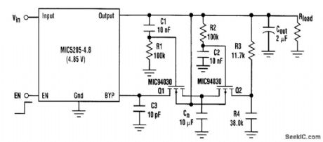
The MIC5205 is a low-dropout PNP regulator that incorporates a noise bypass pin for additional noise reduction. A single 10-nF capacitor, connected from the bypass pin to ground, reduces output noise by Vout/1.24 V (12 dB for the 5-V part) and creates a noise pole below 100 Hz. Switch-on time is increased from 80 μs to 15 ms. With the addition of a few components, the following circuit preserves a low switch-on time. A low-to-high signal on EN switches the output on quickly. This allows R1 and C1 to hold Q1 off while R2 and C2 hold Q2 on. Cn is also quickly charged to the bypass pin voltage through Q2 by the voltage divider R3, R4. C1 and C2 then charge to the output voltage,turntng Q1 on and Q2 off. Cn is now switched from the voltage divider to the bypass pin. The regulator is now in the low-noise configuratipn, which takes about 100 μs. When EN goes low, C1 and C2 discharge through R1, R2, R3, R4, and Rload. This resets the circuit for the next turn-on cycle. C3 helps prevent overshoot on the output. Ratio R3/R4 can be found empirically: First, set the ratio close to the ratio 1.24 V/(Vout-1.24 V), then adjust the value so the output turns on quickly without overshoot. The final tolerance needs to be 1 percent. Switch-off time is determined only by output capacitor size and the load. (View)
View full Circuit Diagram | Comments | Reading(984)
LIGHT_PEN_AMPLIFIER
Published:2009/7/16 20:39:00 Author:Jessie

Consists of four two-transistor wideband-amplifier modules, each withinverse feedback to hold current gain at 21 with high stability.Interstage coupling networks raise lower cutoff frequency to 500 cps, to provede some rejection of 120-cps room light picked up by photodiode.-B.M. Gurley and C.E.Woodward,Light-Pen Links Computer to Operator,Electronics,32:47,p 85-87. (View)
View full Circuit Diagram | Comments | Reading(725)
MINI_MEGAPHONE
Published:2009/7/13 1:35:00 Author:May

The mini megaphone is composed of an electret microphone (MIC1), an LM386 low-voltage audio-power amplifier (U1), a horn speaker (SPKR1), and a few other components. (View)
View full Circuit Diagram | Comments | Reading(5460)
SIMPLE_WATTMETER
Published:2009/7/16 20:37:00 Author:Jessie
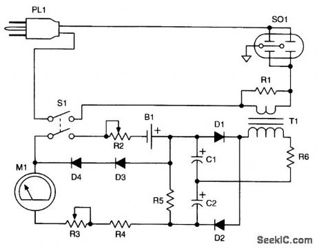
A current transformer (T1) is used to derive a larger ac voltage, which is rectified by D1and D2 to produce a dc voltage proportional to ac line current. B1, R2, and D3, and D4 are used to linearize the circuit. (View)
View full Circuit Diagram | Comments | Reading(847)
10_min_TIMER
Published:2009/7/13 1:35:00 Author:May


Uses SN74121 as actableMVBR generating pulses at 4-s intervals, U2 and U3 divide pulsetrain by 144 to give period of 576s U4 is then turned on, producing positive output pulse lasting 20 s that turns on Q1 for driving keyer, sidetone oscillator, lamp, or other signaling device as reminder for amateur radio operator to make 10-min station identification. R1 adjusts timing.-H. Seeger, Ten-Minute Timer, Ham Radio, Nov. 1976, p 66.
(View)
View full Circuit Diagram | Comments | Reading(1182)
FOCUS_COLT_REGULATOR
Published:2009/7/16 20:36:00 Author:Jessie

Regulation is 0.5% for current range of 220 to 270 ma, for magnetic focus coil of crt, between 25℃ and 65℃.-A.E. Popodi, Reliable Repertoire Of Display Circuits,Electronics,38:2,p 60-66. (View)
View full Circuit Diagram | Comments | Reading(618)
AC_WATTMETER_CIRCUIT
Published:2009/7/16 20:35:00 Author:Jessie
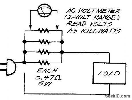
A true wattmeter is a complicated instrument. But if all the wattages that you want to measure are at the same voltage (120 Vac) and the loads are resistive (such as lights, heaters, or motors under load), you can just pass the current through at 0.12-Ω resistance (four 0.47-Ω, 5-W resistors in parallel), connect an ac voltmeter across the resistance, and read volts as kilowatts. That is, every volt across the resistance corresponds to 1000 W (equal to 8 A) drawn by the load. Remember that the voltmeter terminals are hot; use insulated pin sockets so that you won't touch the contacts accidentally. On inductive or capacitive loads, such as unloaded motors or transformers and computer power supplies, your wattmeter will read high because the current and voltage are not in phase. (View)
View full Circuit Diagram | Comments | Reading(1833)
RASTER_DISPLAY
Published:2009/7/16 20:35:00 Author:Jessie

Sixteen digital words can be displayed simultaneously on ordinary scope, For troubleshooting in data processors. Sweep generators are controlled by two-bit gap between words.-B. S. While, Circuit Converts One-Trace Scopes to Raster Display, Electronics, 36:48, p 33-35. (View)
View full Circuit Diagram | Comments | Reading(926)
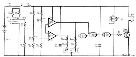
Infrared automatic tap controller circuit
Published:2011/8/4 3:29:00 Author:May | Keyword: Infrared, automatic, tap controller

The diagram shows infrared automatic tap controller circuit. This controller circuit includes transmitting circuit and receiveing decoder control circuit. The transmitting circuit is composed of multivibratorand infrared transmitting diode; receiving circuit consists of infrared receiving tubes D1 and D2, operational amplifier IC2(CA741), tone decoder IC3(LM567), AC solid state relay IC4(SP110), power supply circuit and so on.
In the transmitting circuit, multivibrator consists of IC1(555) and R1, R2, C1, etc, and its oscillator frequency f=1.44/(R1+2R2)C1, the corresponding frequency of the parameter isshown in the picture and itis about 40KHz. Oscillator output signal can drive TLN104 LED1~LED3 work to generate infrared pulse modulated wave. (View)
View full Circuit Diagram | Comments | Reading(1496)
Z_AXLS_MARKER_GENERATOR
Published:2009/7/16 20:32:00 Author:Jessie

Circuit provides high-intensity dot marker on trace at any desired frequency in range from 8 to 22 Mc, in two overlapping ranges, with better than 1% long-term accuracy. Z-axis pulse is generated when external swept r-f oscillator passes through frequency to which tank circuit is tuned.-D.J. Odorizzi, Z-Axis Marker Generator for Bandpass Circuit Alignment, EJectronics,33:26,p 108-110. (View)
View full Circuit Diagram | Comments | Reading(728)
POWER_CHECK
Published:2009/7/16 20:31:00 Author:Jessie
This system is basically an ammeter with a tricolor LED readout in place of a conventional meter. In this system, the tricolor LED shows green for a low demand, yellow for a medium one (acceptable for a temporary heavy load, such as a water pump), and red to indicate excessive use and the need to switch appliances off right away. When red shows, an audible signal is also given. The circuit is built in a small metal box, with the LED mounted on the front panel. A piece of terminal block inside is used to make the connections to the external system.
This circuit must not be used in installations using more than 10A. Having said that, though, the values at which the colors operate are freely adjustable. In the prototype unit, a current below 2A was judged to be low; one between 2 and 4A, medium; and one more than 4A, high. With these criteria, by keeping green, at least 20 hours of operation would be obtained from a standard 60-Ah battery. (View)
View full Circuit Diagram | Comments | Reading(1085)
The circuit using three switches to control a lamp
Published:2011/7/19 10:26:00 Author:Nancy | Keyword: three switches , a lamp

In some conditions, we need to control a lamp in three places, and at this time two single-pole double-throw switches and a double-pole-double-throw switch are needed, they are connected shown as the the figure. (View)
View full Circuit Diagram | Comments | Reading(662)
HIGH_GAIN_AMPLIFIER
Published:2009/7/13 1:34:00 Author:May
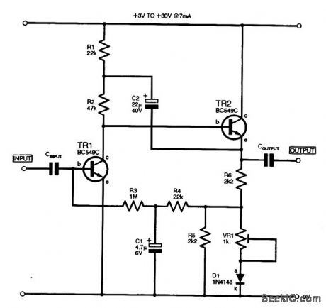
This high-gain inverting amplifier stage was designed to operate with a rail of between 3 and 30 V. It includes a bootstrap network (R1, C2), which serves to increase the gain of the stage to approximately 3000, as well as offering a low-distortion output waveform at maximum amplitudes. The input impedance is approximately 80 kV at 200 Hz, the output level is 80 percent at 20 kHz, and noise at the output is 14 mV p-p. R5 and D1 were included to proportionately lower the bias to TR1 to compensate for any increases in the rail voltage; R5 can be omitted and Dl shorted out if the rail is con-stant. VR1 is adjusted to give symmetrical clipping of the maximum output signal.
(View)
View full Circuit Diagram | Comments | Reading(1800)
TEST_SEOUENCING
Published:2009/7/13 1:33:00 Author:May
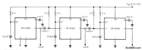
Uses 555 timers connected sequentially. With values shown, first timer runs for 10 ms after starting with pulse at terminal 2 or by grounding 2. At end of timing cycle, second circuit runs for 50 ms before triggering third circuit having 10-ms delay. Each timer controls its own load, as required for sequencing of automatic tester.-E. R. Hnatek, Put the IC Timer to Work in a Myriad of Ways, EDNMagazine, March 5, 1973, p 54-58. (View)
View full Circuit Diagram | Comments | Reading(1904)
| Pages:728/2234 At 20721722723724725726727728729730731732733734735736737738739740Under 20 |
Circuit Categories
power supply circuit
Amplifier Circuit
Basic Circuit
LED and Light Circuit
Sensor Circuit
Signal Processing
Electrical Equipment Circuit
Control Circuit
Remote Control Circuit
A/D-D/A Converter Circuit
Audio Circuit
Measuring and Test Circuit
Communication Circuit
Computer-Related Circuit
555 Circuit
Automotive Circuit
Repairing Circuit