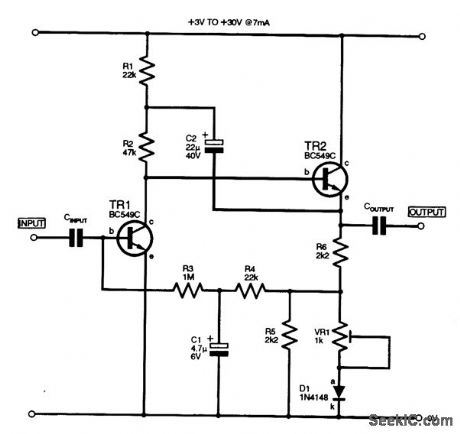
Amplifier Circuit
HIGH_GAIN_AMPLIFIER
Published:2009/7/13 1:34:00 Author:May | From:SeekIC

This high-gain inverting amplifier stage was designed to operate with a rail of between 3 and 30 V. It includes a bootstrap network (R1, C2), which serves to increase the gain of the stage to approximately 3000, as well as offering a low-distortion output waveform at maximum amplitudes. The input impedance is approximately 80 kV at 200 Hz, the output level is 80 percent at 20 kHz, and noise at the output is 14 mV p-p. R5 and D1 were included to proportionately lower the bias to TR1 to compensate for any increases in the rail voltage; R5 can be omitted and Dl shorted out if the rail is con-stant. VR1 is adjusted to give symmetrical clipping of the maximum output signal.
Reprinted Url Of This Article:
http://www.seekic.com/circuit_diagram/Amplifier_Circuit/HIGH_GAIN_AMPLIFIER.html
Print this Page | Comments | Reading(3)

Article Categories
power supply circuit
Amplifier Circuit
Basic Circuit
LED and Light Circuit
Sensor Circuit
Signal Processing
Electrical Equipment Circuit
Control Circuit
Remote Control Circuit
A/D-D/A Converter Circuit
Audio Circuit
Measuring and Test Circuit
Communication Circuit
Computer-Related Circuit
555 Circuit
Automotive Circuit
Repairing Circuit
Code: