
Circuit Diagram
Index 732
SCR_SWITCHING
Published:2009/7/16 10:20:00 Author:Jessie

Scr's switch 0.75 amp into solenoid load at 20 cps with high reliability, simplicity, and low cost. For monostable mode, remove supply voltage form B and apply single +150-V pulse to A.-H. D. Valliant, Scr Multivibrator Switches Reliably, Electronics,38:5, p 95. (View)
View full Circuit Diagram | Comments | Reading(644)
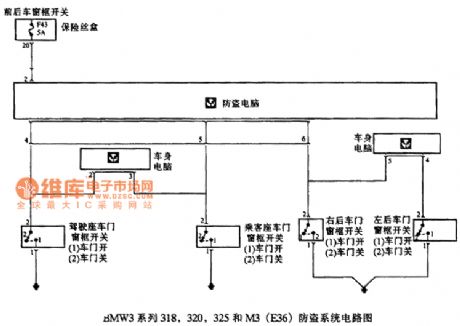
BMW3 series 318,320,325 and M3(E36) anti-theft system circuit 1
Published:2011/7/19 10:39:00 Author:Nancy | Keyword: BMW3 series, anti-theft system
View full Circuit Diagram | Comments | Reading(385)
Chevrolet Lou mitag (2.2L) sedan electronically controlled fuel injection, no distributor ignition circuit diagram
Published:2011/8/4 2:08:00 Author:Ecco | Keyword: Chevrolet Lou mitag , 2.2L sedan , electronically controlled, fuel injection , no distributor ignition
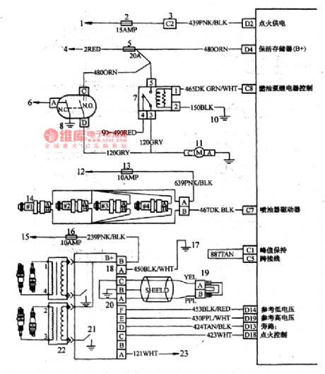
1,12,15 - the ignition switches; 2- ECM fuse; 3-wire bulkhead connector; 4- power supply battery; 5- sleeve fuel pump / ECM fuse;6- dashboard; 9- fuel pump test terminal; 10,17 -engine ground; 11- fuel pump (in tank); 13- fuel injector fuse; 14- fuel injector; 16-point electrical fuse; 18- ground; 19- crankshaft position sensor; 20- signal; 21- electronic ignition control module; 22- fire coil; 23- tachometer.
(View)
View full Circuit Diagram | Comments | Reading(1549)
Liquid level automatic controller circuit diagram 5
Published:2011/8/4 2:32:00 Author:Ecco | Keyword: Liquid level , automatic controller

The liquid level automatic controller circuit is composed of the power supply circuit and level detection circuit control circuit, and it is shown as the chart. Power supply circuit is composed of the knife switch Q, fuses FU1, FU2, power switch S1, power transformer T, bridge rectifier UR and filter capacitor C. Liquid level detection control circuit consists of reeds SA1, SA2, relays K1, K0, thyristor VT, resistor R, AC contactor KM, thermal relay KR, control buttons S2, S4 and manual / automatic control switch S3. HL1 and HL2 are the power and working indicator lights.
(View)
View full Circuit Diagram | Comments | Reading(848)
380MHz linear amplifier circuit composed of RF2175
Published:2011/8/4 3:18:00 Author:May | Keyword: linear amplifier, 380MHz

Radio-frequency signal ( RF) is input by pin 6 andoutput by pin 12, 13 after being enlarged by preamplifier, final amplifier. Pin 6 is directly coupled with inside amplifier, so we must add a blocking coupling capacitor. Pin 12 and 13 are used as the final stage power amplifier power supply end, which can provide bias current for the final amplifier. pin 14 is used as the second harmonic filter circuit, which uses the transmission lines or inductor and capacitor to form filter with resonance in 2f0, and it can provide low impedance path for the second harmonic, which can effectively short the second harmonic. (View)
View full Circuit Diagram | Comments | Reading(713)
Liquid level automatic controller circuit diagram 4
Published:2011/8/4 2:29:00 Author:Ecco | Keyword: Liquid level , automatic controller

The liquid level automatic controller circuit is composed of the power supply circuit, liguid level detecting control instruction circuit, starting control circuit, and it is shown. Power supply circuit is composed of the power transformer T, bridge rectifier and filter capacitor C. Liquid detecting control instruction circuit is composed of electrodes a ~ c, six NOT gate IC (D1 ~ D6), resistors R1, R2, relay K, color light-emitting diode VL and diode VD. R1 and R2 use 1/4W carbon film resistors or metal film resistors. C selects the aluminum electrolytic capacitor with voltage in 25V.
(View)
View full Circuit Diagram | Comments | Reading(963)
VOLTAGE_DIVIDER
Published:2009/7/16 20:19:00 Author:Jessie
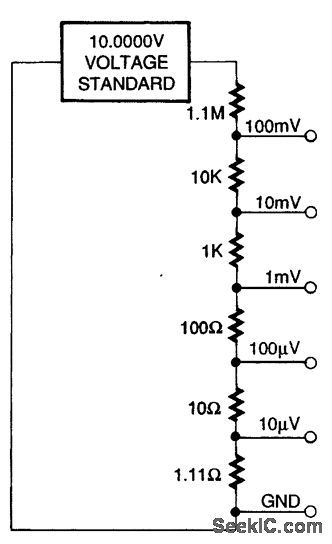
This divider will produce low dc voltages from a 10-V supply. The resistor values can be scaled proportionally for other requirements. (View)
View full Circuit Diagram | Comments | Reading(866)
BROADBAND_RF_TESTER
Published:2009/7/16 20:18:00 Author:Jessie

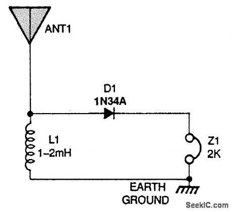
This circuit is useful for crystal radio experimenters for evaluating an antenna and ground setup If you hear some signals, a crystal set will probably work with the antenna and ground. (View)
View full Circuit Diagram | Comments | Reading(981)
SIGNAL_TRACER
Published:2009/7/16 20:16:00 Author:Jessie
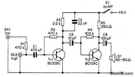
The signal tracer has good sensitivity, so it can be used for any normal type of audio signal tracing. The circuit provides AM demodulation, and the signal tracer can therefore be used for IF and RF testing on AM radios, provided that a suitably strong antenna signal is available. The unit has an integral loudspeaker, and although the maximum output power is only a few tens of milliwatts, the volume level obtained is more than adequate for this application. If preferred, though, the loudspeaker can be replaced by an earpiece or headphones. Low-, medium-, and high-impedance headphones are all suitable for use with the unit. (View)
View full Circuit Diagram | Comments | Reading(0)
ELECTRONIC_STETHOSCOPE
Published:2009/7/16 20:15:00 Author:Jessie
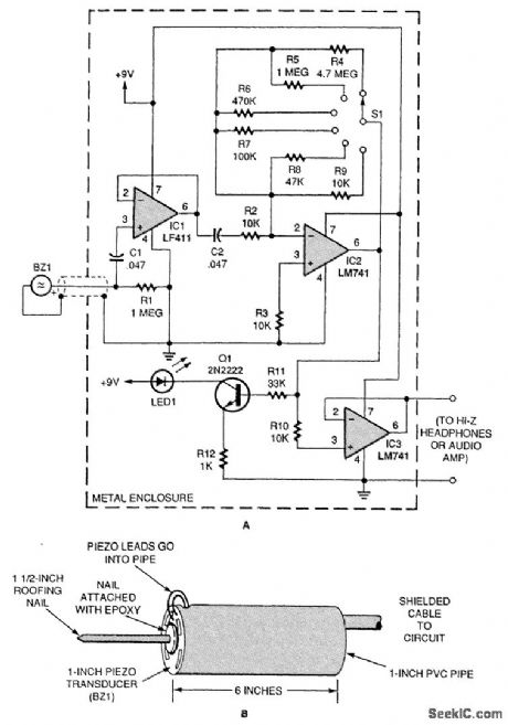
Most electronic stethoscope circuits feature a microphone assembly. Here's one based on a piezo disk used as the transducer. Using 5-min epoxy, glue a roofing nail to the center of the top side of a piezo disk. Be generous with the epoxy, and lay a bead over the top of the nail head. Later, epoxy the outer rim of the backside of the disk to a 1-in diameter PVC pipe roughly 6 in in length, which will serve as a handle. Attach a shielded cable from the piezo-disk leads and secure them in place. The piezo disk's signal is coupled by the cable to IC1, an LF411 FET op amp configured as a buffer. The LF411's output is coupled to IC2, an LM741 op amp configured for high gain. Resistors R4 to R9 set the gain via a rotary switch, but a potentiometer could be used instead. The amp's output goes to both IC3 (a final buffer stage) and Q1 (an MPS7965 general-purpose NPN transistor). The output of the final buffer IC3, an LM741, is connected to high-impedance headphones or a small LM386-based audio amplifier. Power is supplied by two 9-V batteries configured as a split supply. (View)
View full Circuit Diagram | Comments | Reading(908)
PULSE_COUNTING_CIRCUIT_FOR_SHAFT_ENCODERS
Published:2009/7/16 20:11:00 Author:Jessie

The output pulses of an encoding circuit can be counted with a BCD up/down counter such as the 40192. A binary-coded-decimal (BCD) number is produced. The counters have separate up and down clock inputs. For example, as long as the COUNT input (pin 11) is high, the counter will increment one count for every positive edge at the CLOCK-UP input (pin 5), and decrement one count for every positive edge at the CLOCK-DOWN input (pin 4). Counters can be cascaded by connecting the BORROW output (pin 13) to the following CLOCK-DOWN input and the CARRY output (pin 12) to the following CLOCK-UP input. (View)
View full Circuit Diagram | Comments | Reading(3259)
TIME_AND_PERIOD_ADAPTER
Published:2009/7/16 20:10:00 Author:Jessie
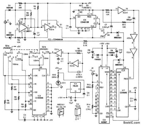
This circuit enables time period measurements to be made on a DMM. Integrated circuit IC1, an LM311 comparator, conditions the input waveform for the 5-V logic required by the circuit. The gate signal is applied to IC7, a CD4040B CMOS 12-stage binary counter, to measure pulse width, or through IC5, a CD4013B CMOS dual flip-flop, to measure time period. Integrated circuit IC2, a CD4069UB CMOS hex inverter, provides the precision 2.000-MHz crystal-controlled pulse train for IC3, a CMOS divide-by-N counter. It divides the pulse train by 1, 10,100,1000,or10,000 to cover the five ranges selected by rotary selector switch 52. The divider's output is gated by the input pulse at IC7 through a resistor-diode NOR gate. Integrated circuit IC4, a 78L05 voltage regulator, supplies +5V to the circuit; IC2-d, IC2-e, and IC2-f provide the properly timed RESET signal for IC7 and the LATCH ENABLE signal for IC6, an AD567 digital-to-analog converter (DAC), the key component in this adapter. DAC IC6 converts the 12-bit count stored in IC7 to a negative output current. That current is converted to a negative voltage by the combination of R13 and R14. The voltage is sent to a DMM at jack J2 over a twisted-wire pair terminated with a phono plug at one end and a suitable matching plug for the DMM at the other end. (View)
View full Circuit Diagram | Comments | Reading(1505)
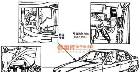
BMW3 series anti-theft component location circuit
Published:2011/7/19 10:40:00 Author:Nancy | Keyword: BMW3 series , anti-theft , component location
View full Circuit Diagram | Comments | Reading(555)
100_CPS_TO_1_MC_ASTABLE
Published:2009/7/16 13:08:00 Author:Jessie

Gives frequency change of 10,000 with reasonably good linearity over most of operating range. Two parts of timing cycle can be varied independently over wide range.-W. J. Mattox, A Versatile, Very-Wide Range Multivibrator, EEE, 13:7, p 59-61. (View)
View full Circuit Diagram | Comments | Reading(720)
AM_DEMODULATOR
Published:2009/7/16 7:00:00 Author:Jessie

Signetics ULN2209 IC provides 55-dB gain for input signal and sym-metrical limiting above 400 μV. Limited carrier is then applied to MC1496K balanced modulator-demodulator transistor array for demodulation. Output filtering is required to remove high-frequency sum components of carrier from audio signal. Output amplitude is maximum when phase difference between signal and carrier inputs is 0°.- Signetics Analog Data Manual, Signetics, Sunnyvale, CA, 1977, p 757-758. (View)
View full Circuit Diagram | Comments | Reading(0)
432_MHz_PREAMP
Published:2009/7/16 6:59:00 Author:Jessie

Developed as part of 400-MHz radiotelescope, for low-noise operation. Gain is 12 dB, and noise figure is below 2 dB. Circuit is basic common-emitter amplifier with tuned input and output. Neither neutralization nor shielding are needed. Supply can be 9-V transistor radio battery. Current drain is 3mA. L1 and L2 are each 1 turn No. 16 wire3/8 inch in diameter, with L2 center-tapped.-S. A, Maas, An Inexpensive Low Noise Preamplifier for 432 MHz, QST, Jan. 1975, p 21-22. (View)
View full Circuit Diagram | Comments | Reading(1657)
LIMITER_DETECTOR
Published:2009/7/16 6:50:00 Author:Jessie
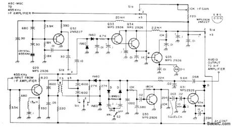
Used in all-band double-conversion superheterodyne receiver for AM, narrow-band FM, CW, and SSB operation. Q29 acts as limiter on FM but on AM is 455-kHz amplifier whose RF output is coupled to 1N60 AGC rectifier pair connected as voltage doubler that provides bias for AGC amplifier Q33-Q34. Output of Q29 is coupled to detector by T3. Although detector is actually phase discriminator, mode switch connects circuit as half-wave rectifier for AM and CW/SSB. On CW/SSB (S1 on 1), AGO rectifier is disconnected and AGC diodes receive bias from manual gain-control pot. BFO is then energized and connected to T3. Output of diode detector feeds squelch and audio stages. Supply is 13.6 V regulated. Article gives all circuits of receiver.-D. M. Eisenberg, Build This All-Band VHF Receiver, 73 Magazine, Jan.1975, p 105-112. (View)
View full Circuit Diagram | Comments | Reading(1448)
Liquid level automatic controller circuit diagram 3
Published:2011/8/4 2:23:00 Author:Ecco | Keyword: Liquid level , automatic controller

The liquid level automatic controller circuit is composed of the power supply circuit, level detection circuit and control implementation circuit, and it is shown as the chart. Power supply circuit is composed of the power transformer T, rectifier diodes YD1 ~ VD4 and filter capacitor C. Level detection circuit is composed of the high level electrode A, low level electrode B and the main electrode C. Control implementation circuit consists of the relay K, control transistor V and AC contactor KM. R1 and R2 select 1/4W carbon film resistors. C select the aluminum electrolytic capacitor with voltage in 16V. VD1 ~ VD5 use 1N4001 or 1N4007 silicon rectifier diodes.
(View)
View full Circuit Diagram | Comments | Reading(853)
DOUBLE_BALANCED_MIXER_1
Published:2009/7/16 6:48:00 Author:Jessie

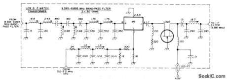
Uses Watkins-Johnson M6 low-level hot-carrier-diode double-balanced mixer as replacement for FET second mixer amateur-band dual-conversion receiver to reduce intermodulation distortion.U310, CP643, or CP651 can be used in place of U320 high-transconductance JFET. Pi-network output circuit couples 2000-ohm output of JFET stage to 2000-ohm IF filter. All inductance values are in microhenrys.-A. J. Burwasser, Reducing Intermodulation Distortion in High-Frequency Receivers, Ham Radio, March 1977, p 26-30. (View)
View full Circuit Diagram | Comments | Reading(2535)
100_MHz_MIXER
Published:2009/7/16 6:45:00 Author:Jessie

With local oscillator frequency of 70 MHz, opamp provides difference frequency of 30 MHz at high conversion gain. Isolation between oscillator and signal source is excellent.-B. Trout, A High Gain Integrated Circuit RF-IF Amplifier with Wide Range AGC, Motorola, Phoenix, AZ, 1975, AN-513, p 9. (View)
View full Circuit Diagram | Comments | Reading(1652)
| Pages:732/2234 At 20721722723724725726727728729730731732733734735736737738739740Under 20 |
Circuit Categories
power supply circuit
Amplifier Circuit
Basic Circuit
LED and Light Circuit
Sensor Circuit
Signal Processing
Electrical Equipment Circuit
Control Circuit
Remote Control Circuit
A/D-D/A Converter Circuit
Audio Circuit
Measuring and Test Circuit
Communication Circuit
Computer-Related Circuit
555 Circuit
Automotive Circuit
Repairing Circuit