Signal Processing
TIME_AND_PERIOD_ADAPTER
Published:2009/7/16 20:10:00 Author:Jessie | From:SeekIC

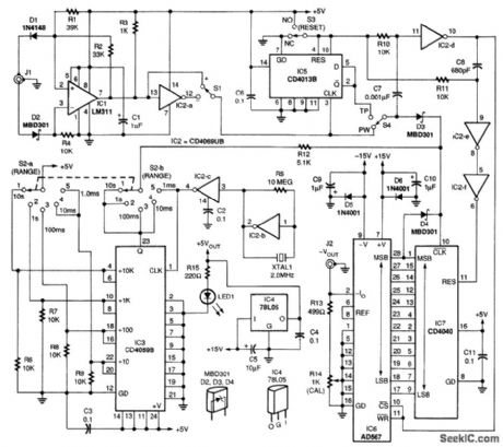
This circuit enables time period measurements to be made on a DMM. Integrated circuit IC1, an LM311 comparator, conditions the input waveform for the 5-V logic required by the circuit. The gate signal is applied to IC7, a CD4040B CMOS 12-stage binary counter, to measure pulse width, or through IC5, a CD4013B CMOS dual flip-flop, to measure time period. Integrated circuit IC2, a CD4069UB CMOS hex inverter, provides the precision 2.000-MHz crystal-controlled pulse train for IC3, a CMOS divide-by-N counter. It divides the pulse train by 1, 10,100,1000,or10,000 to cover the five ranges selected by rotary selector switch 52. The divider's output is gated by the input pulse at IC7 through a resistor-diode NOR gate. Integrated circuit IC4, a 78L05 voltage regulator, supplies +5V to the circuit; IC2-d, IC2-e, and IC2-f provide the properly timed RESET signal for IC7 and the LATCH ENABLE signal for IC6, an AD567 digital-to-analog converter (DAC), the key component in this adapter. DAC IC6 converts the 12-bit count stored in IC7 to a negative output current. That current is converted to a negative voltage by the combination of R13 and R14. The voltage is sent to a DMM at jack J2 over a twisted-wire pair terminated with a phono plug at one end and a suitable matching plug for the DMM at the other end.
Reprinted Url Of This Article:
http://www.seekic.com/circuit_diagram/Signal_Processing/TIME_AND_PERIOD_ADAPTER.html
Print this Page | Comments | Reading(3)

Article Categories
power supply circuit
Amplifier Circuit
Basic Circuit
LED and Light Circuit
Sensor Circuit
Signal Processing
Electrical Equipment Circuit
Control Circuit
Remote Control Circuit
A/D-D/A Converter Circuit
Audio Circuit
Measuring and Test Circuit
Communication Circuit
Computer-Related Circuit
555 Circuit
Automotive Circuit
Repairing Circuit
Code: