
Circuit Diagram
Index 721
GENERAL-PURPOSE_WIDEBAND_PREAMP
Published:2009/7/13 2:42:00 Author:May
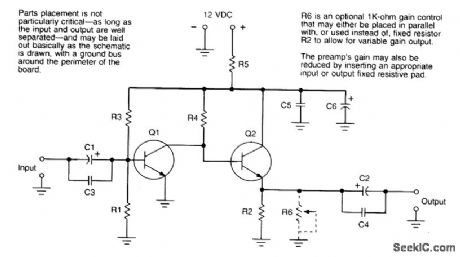
This preamp has a galn of35 dB at 100 kHz,30 dB at 10 MHz,and 17 dB at 100 MHz and draws 15 mA at 12 V. (View)
View full Circuit Diagram | Comments | Reading(904)
BIDIRECTIONAL_PF_AMPLIFIER
Published:2009/7/13 2:41:00 Author:May
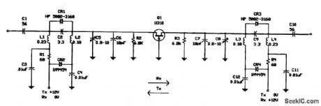
JFETS can often be used with the source and drain interchanged. This interesting circuit makes use of this fact as a bidirectional RE amplifier at 70.0455 MHz. It is useful for transceiver applications. (View)
View full Circuit Diagram | Comments | Reading(1007)
25_W_SOLID_STATE_LINEAR_AMPLIFIER
Published:2009/7/13 2:39:00 Author:May

This shows a schematic diagram of the 25-W linear amplifier. Decimal-value capacitors are in microfarads; others are in picofarads. Polarized capacitors are electrolytic or tantalum, 16 V or greater. Resistors other than R5 are 1/4-W carbon-composition or carbon-film units. (View)
View full Circuit Diagram | Comments | Reading(2326)
N100-multifunctional power control integrated circuit
Published:2011/7/27 10:17:00 Author:Nancy | Keyword: multifunctional power control


The N100 is a multifunctional power control integrated circuit widely used in the Nokia mobile phones.
Functions and features:The N100 integrated circuit includes sleep work mode option, various voltage stabilizer circuits, pulse width modulation circuit, RF power supply control circuit, the battery type detection circuit, temperature detection circuit batteries, SIM card powered start, data, reset, clock, input/output control circuit, the universal serial data and clock, the main clock temperature testing, charging current and voltage detection circuit, and some other auxiliary function circuits.
(View)
View full Circuit Diagram | Comments | Reading(1480)
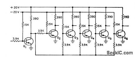
MAJORITY_GATE
Published:2009/7/16 5:09:00 Author:Jessie
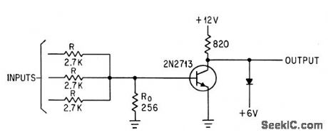
With odd number of inputs and resistor-summer, threshold logic transistor is virtually off up to 0.5 V base-emitter voltage and on at 0.7V. Output is inverted.-W. A. Sauer, How to Achieve Majority and Threshold Logic with Semiconductors, Electronics, 36:48, p 23-25. (View)
View full Circuit Diagram | Comments | Reading(894)
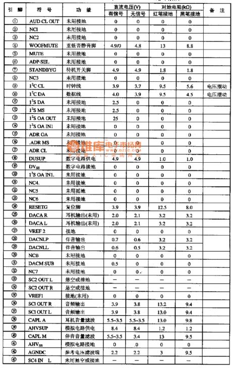
MSP3463G-audio signal processing integrated circuit
Published:2011/7/27 10:07:00 Author:Nancy | Keyword: audio signal
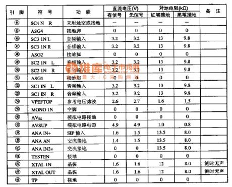
The MSP3463G is a new generation audio signal processing integrated circuit widely used in Konka S series wide screen color TV.
1.Functions and features:The MSP3463G integrated circuit contains I2C bus interface circuit, I2S bus interface circuit, earphone audio amplifier circuit, standby switching circuit, heavy bass mute circuit, and some other auxiliary function circuits. 2. Pin function and data:
The MSP3463G integrated circuit adopts 64 DIP package, which is used in the Konka P2960S, P2971S mirror color TV. The pin function and data is shown as the table. (View)
View full Circuit Diagram | Comments | Reading(639)
VHF_REGENERATIVE
Published:2009/7/16 5:09:00 Author:Jessie
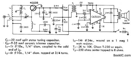
Covers 2-meter amateur band, 152-174 MHz public-service channels including 162.5-MHz weather service, and number of other services. performance is good enough for use as emergency communication receiver. Supply should be six D cells in series; cheaper 9-V transistor radio batteries may have too much impedance and cause motor-boating.-S. Kelly, A Solid State V.H. F. Regenerative Receiver, CQ, March 1970, p 63-64. (View)
View full Circuit Diagram | Comments | Reading(1184)
28_30_MHz_SATELUTE_PREAMP
Published:2009/7/16 5:08:00 Author:Jessie

Low-noise design provides up to 25-dB gain and typical noise figure of 1 dB, using dual-gate MOSFET in cascode circuit. Adjust C1 and C2 for maximum output. Developed for use at input of communication receiver. Drain from 12-V power supply should be 3 to 7 mA; if too low or too high, adjust value of R1.-J. Reisert, Jr., Low Noise Figure 28-30 MHz Preamplifier for Satellite Reception, Ham Radio, Oct. 1975, p 48-51. (View)
View full Circuit Diagram | Comments | Reading(862)
NOR_CIRCUIT
Published:2009/7/16 5:04:00 Author:Jessie
With 2N834 epitaxial mesa transistors, turn-on time. is 80 nsec, and turn off 90 nsec, as compared to 111-nsec turn-on and 140.nsec turn-off for nonepitaxial 2N706 mesa transistors in same circuit.-W. D.Roehr, Epitaxial Process Improves Transistor Characteristics, Electronics, 34:9, p 52-53. (View)
View full Circuit Diagram | Comments | Reading(787)
TUNNEL_DIODE_OR_GATE
Published:2009/7/16 5:04:00 Author:Jessie
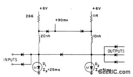
Two monoslable multivibrators are cascaded to provide cur rent gain at 200 Mc. Output is obtained when either of input currents rises above 8 ma.-E. Gottlieb and J. Giorgis, Tunnel-Diode Switching Circuits, Electronics, 36:27, p 26-31. (View)
View full Circuit Diagram | Comments | Reading(0)
74HCT4538N double precision monostable multivibrator integrated circuit
Published:2011/7/27 10:26:00 Author:Nancy | Keyword: double precision , monostable multivibrator
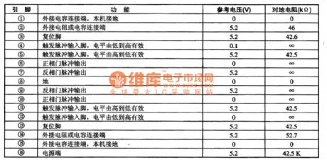
The 74HCT4538N is a double precision monostable multivibrator integrated circuit widely used in TV, audio, VCD, computers and monitors, and other electrical equipment.
The 74HCT4538N integrated circuit includes two monostable multivibrators with the same function inside. It can replace directly the model CC4538β. The IC uses DIP package widely used in the BaiHong DT2000 type frequency doubling wide screen color TV. The pin function and data is shown as table 1. (View)
View full Circuit Diagram | Comments | Reading(523)
EMITTER_COUPLED_MVBR
Published:2009/7/16 5:03:00 Author:Jessie
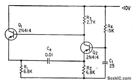
When Q1 conducts, Q2 is cut off and conversely. Duration of both quasi-stable states is controlled by Ce. Q2 should saturate when conducting, to prevent distortion in flat tops of rectangular output pulses.-B. Rakovic, One More Transistor makes a Linear Sawtooth, Electronics, 35:49, p 50-51. (View)
View full Circuit Diagram | Comments | Reading(578)
TUNNEL_DIODE_AND_GATE
Published:2009/7/16 5:03:00 Author:Jessie

Three cascaded monostable multivibrators provide required gain at 200 Mc.-E. Gottlieb and J. Giorgis, Tunnel-Diode Switching Circuits, Electronics, 36:27, p 26-31. (View)
View full Circuit Diagram | Comments | Reading(0)
UNIJUNCTION_CONTROL_0F_MVBR
Published:2009/7/16 5:03:00 Author:Jessie

Transistor mvbr trigger for scr inverter is controlled by unijunction relaxation oscillator Q1. Squarewave output of T1 is required for triggering some inverter circuits.-D. V. Jones, Tum-Off Circuits for Controlled Rectifiers, Electronics, 33:32, p 52-55. (View)
View full Circuit Diagram | Comments | Reading(587)
TWO_TRIODE_CASCODE_MULTIVIBRATOR
Published:2009/7/16 5:01:00 Author:Jessie

Two capacitors in voltage-divider storage circuit control dual-triode multivibrator to produce linear sawtooth waveform, square wave,sine wave, or pulse.-C. Sing, Advantages of Free-Running Cascode Multivibrators,Electronics, 37:5, p 28-29. (View)
View full Circuit Diagram | Comments | Reading(695)
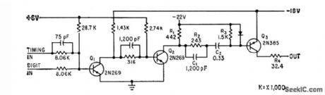
160_METER_PREAMP
Published:2009/7/16 5:01:00 Author:Jessie

Broadband 40-dB preamp has response range extending from broadcast band through VHF. Upper 3-dB point of amplifier is at 65 MHz. Heavy feedback stabilizes gain and provides 50-ohm characteristic.-D. DeMaw, Beat the Noise with a Scoop Loop, QST, July 1977, p 30-34.
(View)
View full Circuit Diagram | Comments | Reading(3000)
Digital integrated circuit diagram
Published:2011/7/13 9:50:00 Author:Nancy | Keyword: Digital integrated circuit
The digital circuit has some advantages: (1)high stability; (2)processing precision is not limited by the pin; (3)logical calculus and judgement function; (4)digital information can be stored for long time, etc. The above advantages of the digital circuit make the digital integrated circuit develop rapidly. Now the digital integrated circuit has been widely used in the national economy and people's life and is expanding its range of application in a high speed. (View)
View full Circuit Diagram | Comments | Reading(426)
MEMORY_DRIVER
Published:2009/7/16 5:00:00 Author:Jessie
Extract-driver circuit furnishes current to extract information from random-access memory of Burroughs B-251 Visible Record Computer.-G. E. Lund and D. R. Faulis, Expandable Random Access Memories, Electronics, 33:11, p 164-166. (View)
View full Circuit Diagram | Comments | Reading(542)
MAGNETICALLY_COUPLED_MVBR
Published:2009/7/16 5:00:00 Author:Jessie

Nonlinear element T in common-emitter lead stabilizes against temperature variation to within 0.1% over 150℃ range. Output is 100 pps. –M. Ingenito, Magnetically Coupled Multivibrators, Electronics, 36:13, p 42-43. (View)
View full Circuit Diagram | Comments | Reading(612)
RC_COUPLED_BINARY_STAGE
Published:2009/7/16 5:00:00 Author:Jessie

Typical switching times are 30 and 44 millimicrosec.-Philco MAT Transistors for Logic Circuits up to 5 Mc (Philco ad), Electronics, 33:17, p 50. (View)
View full Circuit Diagram | Comments | Reading(560)
| Pages:721/2234 At 20721722723724725726727728729730731732733734735736737738739740Under 20 |
Circuit Categories
power supply circuit
Amplifier Circuit
Basic Circuit
LED and Light Circuit
Sensor Circuit
Signal Processing
Electrical Equipment Circuit
Control Circuit
Remote Control Circuit
A/D-D/A Converter Circuit
Audio Circuit
Measuring and Test Circuit
Communication Circuit
Computer-Related Circuit
555 Circuit
Automotive Circuit
Repairing Circuit