Measuring and Test Circuit
DIODE_MATCHING_CIRCUIT_I
Published:2009/7/16 20:41:00 Author:Jessie | From:SeekIC

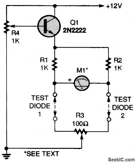
A 2N2222 transistor is connected in an emitter-follower circuit that is powered by a 12-Vdc source. Potentiometer R4 sets the voltage feeding the diodes under test. Two 1000-0,1percent resistors, RI and R2, make up two legs of a four-element bridge circuit. The diodes you want to test make up the other two legs. Potentiometer R3 is a fine-balance control. Meter M1is a 100-0-100-μA, center-zero unit. Connect jumpers in place of the test diodes, set RC to midposition, and set R4 to its maximum-voltage position (minimum resistance).Apply power and adjust R3 for a zero meter reading. Disconnect the power, set R4 to its minimum-voltage position (maximum resistance), and connect two diodes in the test positions. Slowly in-crease the bridge voltage with R4 and watch the meter for any change. The diodes are perfectly matched if the meter remains at zero as the voltage is increased.
Reprinted Url Of This Article:
http://www.seekic.com/circuit_diagram/Measuring_and_Test_Circuit/DIODE_MATCHING_CIRCUIT_I.html
Print this Page | Comments | Reading(3)

Article Categories
power supply circuit
Amplifier Circuit
Basic Circuit
LED and Light Circuit
Sensor Circuit
Signal Processing
Electrical Equipment Circuit
Control Circuit
Remote Control Circuit
A/D-D/A Converter Circuit
Audio Circuit
Measuring and Test Circuit
Communication Circuit
Computer-Related Circuit
555 Circuit
Automotive Circuit
Repairing Circuit
Code: