Amplifier Circuit
STEREO_PREAMP
Published:2009/7/12 23:35:00 Author:May | From:SeekIC

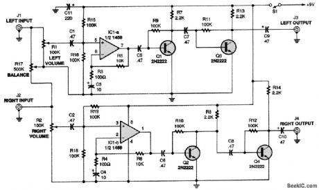
The output of the audio source is fed to the left and right inputs of the circuit (J1 and J2). Potentiometers R1 and R2 control the volumes of the input signals, while potentiometer R17 is a balance control. The incoming signals are coupled through capacitors C1 and C2 to the noninverting inputs of op amps IC1-a and IC1-b. Because IC1 operates as a single-supply amplifier, its output signal fluctuates above and below half of the supply voltage. The output signals of the op amps are coupled to the bases of two 2N2222 transistors (Q1 and Q2), which further amplify the left and right signals. Then, the outputs of the transistors are coupled to the bases of two more 2N2222 transistors (Q3 and Q4), further boosting the left and right signals. The transistor pairs also act as buffers.
Reprinted Url Of This Article:
http://www.seekic.com/circuit_diagram/Amplifier_Circuit/STEREO_PREAMP.html
Print this Page | Comments | Reading(3)

Article Categories
power supply circuit
Amplifier Circuit
Basic Circuit
LED and Light Circuit
Sensor Circuit
Signal Processing
Electrical Equipment Circuit
Control Circuit
Remote Control Circuit
A/D-D/A Converter Circuit
Audio Circuit
Measuring and Test Circuit
Communication Circuit
Computer-Related Circuit
555 Circuit
Automotive Circuit
Repairing Circuit
Code: