Basic Circuit
Long time timing circuit formed by the LM106
Published:2011/7/27 9:49:00 Author:Nancy | Keyword: Long time timing circuit | From:SeekIC

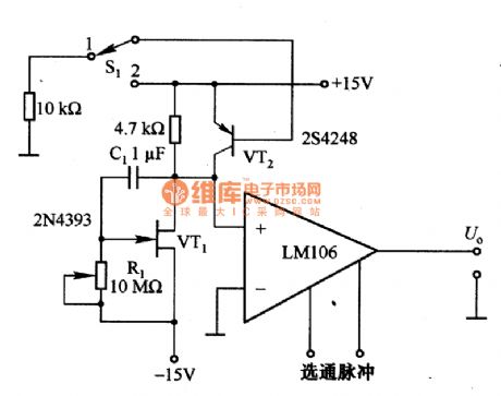
Figure 1 is the long time timing circuit formed by the LM106. The circuit is VT1 (FET tube) mueller integral circuit, if the gain of the circuit is A, the timing constant can be increased to A times. The gain of VT1 is about 60, the equivalent capacitance converted to VT1 grid is increased to 60 times, namely, 60 C1 is equal to 60 μF, and the maximum value of the grid resistance R1 is lOMΩ, so the timing can reach 6005. S1 is a reset switch, it resets when connects to 1 and VT2 conducts, C1 discharges through VT2 and resets to prepare timing for the next time. LM106 is a comparator circuit, the output is connected to corresponding circuit and for timing control.
Reprinted Url Of This Article:
http://www.seekic.com/circuit_diagram/Basic_Circuit/Long_time_timing_circuit_formed_by_the_LM106.html
Print this Page | Comments | Reading(3)

Article Categories
power supply circuit
Amplifier Circuit
Basic Circuit
LED and Light Circuit
Sensor Circuit
Signal Processing
Electrical Equipment Circuit
Control Circuit
Remote Control Circuit
A/D-D/A Converter Circuit
Audio Circuit
Measuring and Test Circuit
Communication Circuit
Computer-Related Circuit
555 Circuit
Automotive Circuit
Repairing Circuit
Code: