About SeekIC | Services | Payment | Advertisements service | Contact Us | Links
© 2008-2012 SeekIC.com Corp.All Rights Reserved.

Published:2011/8/1 8:42:00 Author:TaoXi | Keyword: household appliance, robot, medical equipment, alarm device, infrared sensor, signal processing


The SNS9201 is designed as the human body infrared sensor signal processing circuit that can be used in the household appliance, robot, medical equipment or alarm device applications. The internal circuit is composed of the linear amplifier circuit, the two-way limiter, the voltage comparator, the state controller, the reference power circuit, the signal processor, the delay timer and the blocking timing circuit.
Features
The monolithic design.The wide voltage range, the value is 3-5V.The quiescent current is small, it is about 100uA.The input/output port is easy to control.It uses the CMOS technology.It has the two-way amplitude discriminator.16-pin dual-row DIP package.
(View)
View full Circuit Diagram | Comments | Reading(1397)
Published:2011/8/1 20:29:00 Author:TaoXi | Keyword: electronic toy, audio, RF, infrared decoder

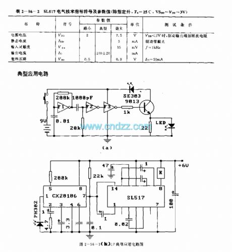
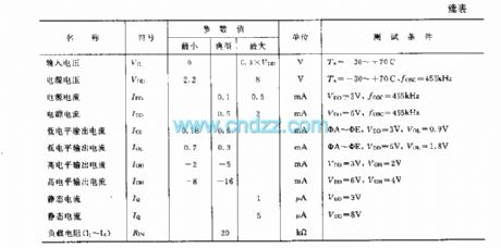
The SL517 is designed as the audio, RF or infrared decoder circuit that can be used in the electronic toy application. The internal circuit is composed of the analog amplifier, the frequency divider, the bistable circuit and the driver.
Features
It uses the CMOS technology.The power voltage range is wide, the value is 2-7.5V.The quiescent current is small (</=5mA).The external components are little.The high sensitivity (</=15mV).The strong anti-interference ability.Bistable output, the driving current is large (100+/-20mA).Simple assembly debugging, stable and reliable performance.
(View)
View full Circuit Diagram | Comments | Reading(2273)
Published:2009/7/8 22:36:00 Author:May

Automatic scaling circuit permits frequent and fast recalibration for precision optical measurements, to compensate for variations in light intensity due to thermal cycling of lamp filament, dirty optics, and gain variations between photodetectors and between amplifiers. With reset pulse at point B, comparator A2 compares output of multiplier to preset reference voltage on R1. If A2 input voltage is greater than reference applied to pin 3 by R2, output switches to zero and remains there until C1 has discharged enough to lower output of A1 and output of multiplier below reference on pin 3. If input at pin 2 ofA2 is less than reference on pin 3,A2 will switch to 15 V and output of multiplier will be adjusted upward until voltage on pin 2 of A2 again exceeds that on pin 3. Output of A2 is thus continually switching between 15 V and 0 V during reset or scaling. After reset pulse is removed, scale factor K is maintained constant by multiplier during measuring.-R. E. Keil, Automatic Scaling Circuit for Optical Measurements, EDN/EEE Magazine, Nov. 15, 1971, p 49-50. (View)
View full Circuit Diagram | Comments | Reading(581)
Published:2009/7/8 22:36:00 Author:May
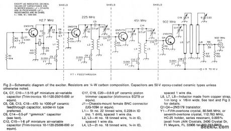
The oscillator, Q1, is a standard overtone circuit. A fifth-overtone crystal, 80.545 MHz, is operated on the seventh overtone, 112.763 MHz. C6 couples the output of the oscillator to Q2, which operates as a doubler to 225.5 MHz. A double-tuned circuit using C7, L2, L3, C10 is used in the collector of Q2 to reduce the level of the 112-MHz oscillator signal. The output of Q2 is capacitively coupled at C11 to the base of Q3. The double-tuned circuit in the collector of Q3 with C12, L4, L5, C15, is tuned to 451 MHz. A small capacitance, 2.7 pF, couples the 451-MHz signal to the base of another 2N5179, Q4, which doubles the signal to 902 MHz. The output of the 902-MHz doubler has a triple-tuned circuit using C17, L6, C19, L7, C20, L8 in its collector.
(View)
View full Circuit Diagram | Comments | Reading(1354)
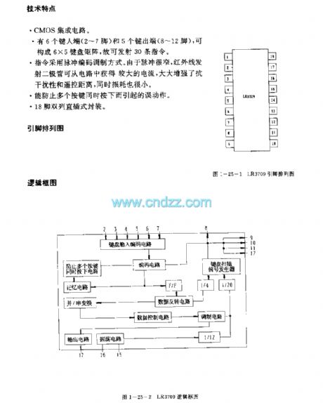
Published:2011/8/1 20:59:00 Author:TaoXi | Keyword: video tape recorder, infrared, remote control, launch circuit

Features
The CMOS IC.It has six input ports (pin-2 to pin-7) and five output ports (pin-8 to pin-12), and they can form the 6X5 keyboard matrix, so this device can launch 30 instructions.The instructions use the pulse coding modulation mode. Because the pulse is narrow, the infrared emission diode can get the large current from the circuit to enhance the anti-jamming performance and the remote distance, also the power consumption is small.It can prevent the error action.18-pin dual-row DIP package.
(View)
View full Circuit Diagram | Comments | Reading(1211)
Published:2009/7/8 22:34:00 Author:May


This field-strength meter is basically a bridge circuit that is equipped with a 0-to-1-mA meter as a readout. (View)
View full Circuit Diagram | Comments | Reading(2851)
Published:2009/7/21 4:43:00 Author:Jessie
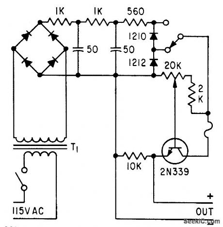
Consists of bridge-rectifier supply with R-C filtering and zener diode regulation, feeding control potentiometer that is isolated from load by grounded-collector transistor. Used as analog voltage source for computer circuit. –E. R. James, Semiconductors Provide Analog Voltage Source, Electronic, 31:33, p 96-100. (View)
View full Circuit Diagram | Comments | Reading(671)
Published:2009/7/8 22:32:00 Author:May

This low-noise amplifier requires no tuning, has a gain of 13 dB, and a typical NF of 0.6 dB at 2.3 GHz. (View)
View full Circuit Diagram | Comments | Reading(518)
Published:2009/7/8 22:31:00 Author:May

Adjustable capacitor C10, and coil L1 form a tank circuit that, in combination with Q1, C2, and R1, oscillates at a frequency on the FM band. The center frequency is set by adjusting C10. An electret microphone, M1, picks up an audio signal that is amplified by transistor Q2. The audio signal is coupled via C9 to Q1, which frequency modulates the tank circuit. The signal is then radiated from the antenna. The circuit can operate from 9-12 Vdc. (View)
View full Circuit Diagram | Comments | Reading(1037)
Published:2011/8/1 20:48:00 Author:TaoXi | Keyword: general, infrared, remote control, launch circuit, dual-tone, multi-frequency, signal generating


The S2559A/D/E/F is designed as the dual-tone multi-frequency signal generating circuit that can be used in the general infrared remote control launch circuit. The internal circuit is composed of the clock circuit, the keyboard input logic control circuit, the programmable frequency divider, the D/A converter circuit and the squelch circuit.
Features
The power supply voltage range is wide:3.5-13V(S2559A/B),2.5-10V(S2559E/F). The power consumption is small.The external crystal frequency is 3.579545MHz.The IC has the weak sound output.It is connected with the telephone keyboard directly.The harmonic distortion is small.Integrated circuit upstream oscillator resistor.The integrated circuit has the reference voltage.It can produce the single-tone.The static operating current is 0.4-1.5uA.The output driving current is 1-10mA.
(View)
View full Circuit Diagram | Comments | Reading(1761)
Published:2009/7/8 22:31:00 Author:May
This circuit provides 14-to 20-dB gam at frequencies from 10 kHz to 30 MHz.The antenna length canbe anything between 5 and 10 feet.A 102-inch CB whip is excellent for this purpose. (View)
View full Circuit Diagram | Comments | Reading(725)
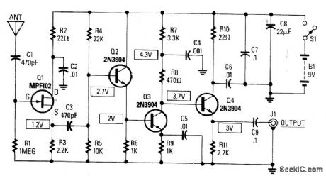
Published:2011/8/1 19:38:00 Author:Zoey | Keyword: Power Line Carrier, Remote Control, Switched Circuit
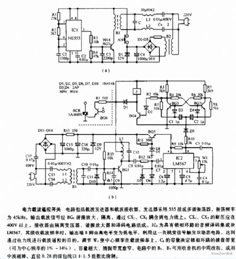
This circuit is composed of carrier transmitter and carrier receiver. The transmitter uses a 555 and is jionted to be a multi-vibrator, whose oscillation frequency is 45kHz. Output carrier signal is amplified and isolated by BG1 resonance and then it is coupled to the power line. The receiver is composed of a isolation transformer, a resonance amplifier and a decoding circuit. (View)
View full Circuit Diagram | Comments | Reading(2077)
Published:2011/8/1 8:58:00 Author:TaoXi | Keyword: video recorder, TV, audio equipment, 30-function, infrared, remote control, launch circuit
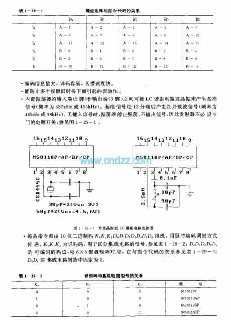

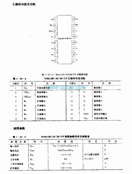
The M50110P/AP/BP/CP is designed as the 30-function infrared remote control launch circuit that can be used in the video recorder, TV and audio equipment applications. The internal circuit is composed of the keyboard input encoder, the instruction decoder, the oscillator, the timing signal generator, the scanning signal generator, the Coding modulator and the output buffer. The difference between the M50110P, M50110AP, M50110BP, M50110CP is the identification number.
Features
It uses the single power operating mode, the power voltage is 2.2-8V.The oscillator will stop operating when the keyboard buttons are not pressed to reduce the power consumption.The duty ratio is small to reduce the power consumption of the diode.The external components are few, the SNR is high, the anti-interference ability is strong.It has six input ports and five output ports to form the 6X5 keyboard matrix.The matching models are M5011P/AP/BP/CP, M50116P/AP/BP/CP and M50117P/AP/BP/CP.
(View)
View full Circuit Diagram | Comments | Reading(1055)
Published:2009/7/8 22:28:00 Author:May

This circuit is designed to make a short pull-up antenna perform like a long wire antenna, while offering no voltage gain. The circuit boosts the receiver's performance only if the signal at the antenna is of sufficient level to begin with.
This circuit takes a short pull-up antenna that has a high output impedance and couples it to the receiver's low input impedance through a two-tran-sistor impedance-matching network. Transistor Q1's high input impedance and high-frequency characteristics make it a good match for the short antenna, and Q2's low output impedance is a close match for the receiver's input. This circuit is usable over the range from 100 kHz to 30 MHz. (View)
View full Circuit Diagram | Comments | Reading(1263)
Published:2009/7/21 4:43:00 Author:Jessie

Color TV chroma demodulator. The ECG1048 is a 14-pin DlPwith an end metal tab. The ECG1089 partially shown is a color processor chip (courtesy GTE Sylvania Incorporated). (View)
View full Circuit Diagram | Comments | Reading(747)
Published:2009/7/8 22:28:00 Author:May

This circuit uses an oscillator (2N2222) and a diode D1 as a nonlinear mixer. The frequency is set by a slug in L1. RFC1, C1, and RFC2 form a low-pass filter to pass video and block rf from the video source. (View)
View full Circuit Diagram | Comments | Reading(1164)
Published:2011/8/1 3:22:00 Author:Zoey | Keyword: High-performance, Infrared, Remote Switch
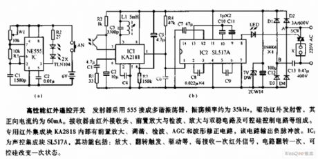
This transmitter uses a connected 555 multi-vibrator to drive the infrared infrared lauch tube, the vibrator's oscillation frequency is about 36kHz and its positive current is about 60mA. The receiver is composed of a infrared receiver head, a pre-amplification and detection circuit, an amplification and bistable circuit and a SCR control circuit. The specilized infrared integrated block KA2818 consists of a pre-amplification, tuning, detection, AGC waveform correction circuit, which inputs negative pulse wave. IC2 is a voice control integrated block SL517A, it has such functions as amplification, trigger flipand drive, etc. Everytime it receives infrared signal, the circuir will filp one time, and the SCR will change its state one time. (View)
View full Circuit Diagram | Comments | Reading(670)
Published:2009/7/8 22:27:00 Author:May

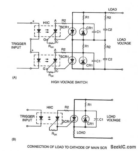
Snubber circuit R2C2, as shown, might be necessary since RI and C1 are tailored for optimized triggering and not for dV/dt protection. Fiber-optic pairs can be used with discrete SCRs to switch thousands of volts. A photon coupler with a transistor output will limit the trigger-pulse amplitude and rise time because of CTR and saturation effects. Using the H11C1, the rise time of the input pulse to the photon coupler is not critical, and its amplitude is limited only by the H11C1 turn-on sensitivity. The load can also be connected to the cathode as illustrated in Fig. 67-3B. (View)
View full Circuit Diagram | Comments | Reading(661)
Published:2011/8/1 21:06:00 Author:TaoXi | Keyword: video tape recorder, infrared, remote control, launch circuit


The LR3710AM is designed as the infrared remote control launch circuit that can be used in the video tape recorder application. The internal circuit is composed of the keyboard input coding circuit, the scanning signal generator, the oscillating circuit, the pulse width modulation circuit, the data control circuit, the data inversion circuit, the parallel serial switching circuit and the output circuit.
Features
It uses the CMOS technology.It can prevent the error action.It is in the 36-pin four-row flat plastic package.
(View)
View full Circuit Diagram | Comments | Reading(1189)
Published:2009/7/21 4:42:00 Author:Jessie

Multiplier circuit using an AD534 multiplier/divider chip (courtesy Analog Devices, Inc.). (View)
View full Circuit Diagram | Comments | Reading(1014)
| Pages:932/2234 At 20921922923924925926927928929930931932933934935936937938939940Under 20 |
Response in 12 hours
© 2008-2012 SeekIC.com Corp.All Rights Reserved.