
Circuit Diagram
Index 933
LR3714M (video tape recorder) infrared remote control launch circuit
Published:2011/8/1 21:13:00 Author:TaoXi | Keyword: video tape recorder, infrared, remote control, launch circuit


The LR3714M is designed as the infrared remote control launch circuit that can be used in the video tape recorder application. The internal circuit is composed of the keyboard input coding circuit, the scanning signal switching circuit, the oscillator, the modulator, the data control circuit, the data inversion circuit, the parallel serial switching circuit and the button pulse output circuit.
Features
It uses the CMOS technology.It can prevent the error action.It is in the 36-pin four-row flat plastic package.
(View)
View full Circuit Diagram | Comments | Reading(1130)
36_KV_OSCILLATOR_TYPE_SUPPLY
Published:2009/7/21 4:41:00 Author:Jessie
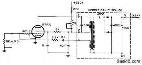
Single pentode in audio oscillator circuit provides sufficient power for step-up transformer and output rectifier filter. Used for dark-face crt. –NBS, Handbook Preferred Circuit Navy Aeronautical Electronic Equpment, Vol. 1, Electron Tube Circuit ,1963, p N14-3. (View)
View full Circuit Diagram | Comments | Reading(548)
Typical_ECG746_Video_IF_Amplifier_and_ECG747_Low_Level_Video_Detector_Circuit
Published:2009/7/21 4:40:00 Author:Jessie

Typical ECG746 Video IF Amplifier and ECG747 Low-Level Video Detector Circuit. (View)
View full Circuit Diagram | Comments | Reading(675)
LR3715M (TV and video recorder) infrared remote control launch circuit
Published:2011/8/1 21:21:00 Author:TaoXi | Keyword: TV, video recorder, infrared, remote control, launch circuit
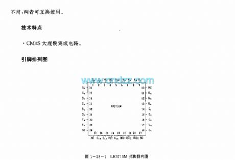
The LR3715M is designed as the infrared remote control launch circuit that can be used in the TV and video recorder applications. The LR3715M has the same technical features, pins arrangement, shape structure, absolute maximum ratings, electrical specifications, logic diagram and the typical applications with the LR3714M. The difference between the LR3715M and LR3714M is the pin-27. The LR3715M's pin-27 is empty, the LR3714M's pin-27 is the C14 port. They can be exchanged if we do not use the pin-27.
Features
The CMOS large scale integrated circuit.
(View)
View full Circuit Diagram | Comments | Reading(852)
Souarer_circuit_using_an_AD532_mutttpter_divider
Published:2009/7/21 4:40:00 Author:Jessie

Souarer circuit using an AD532 mutttpter/divider. This chip is available as a 10-pin TO-100 or a 14-pin DIP (courtesy Analog Devices, Inc.). (View)
View full Circuit Diagram | Comments | Reading(696)
SOLID_STATE_ZERO_VOLTAGE_SWITCHING_ZVS_CIRCUITS
Published:2009/7/8 22:26:00 Author:May
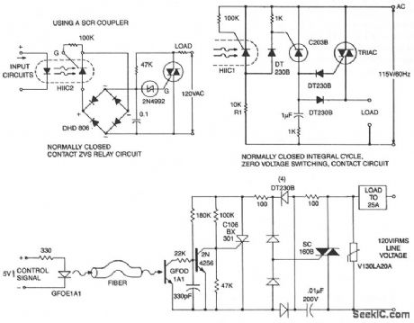
This circuit is effective for lamp and heater loads. Some circuits driving reactive loads require integral cycling and zero-voltage switching-when an identical number of positive and negative half cycles of voltage are applied to the load during a power period. The circuit, although not strictly a relay because of the three-terminal power connection, performs the integral cycle ZVS function when interfaced with the previous coil circuits.
Fiber optics offers advantages in power control systems. Electrical signals do not flow along the non-conducting fiber, minimizing shock hazard to both operator and equipment. EMI/RFI pick up on the fiber is nonexistent-although high gain receiver circuits might require shielding, eliminating noise pick-up errors caused by sources along the cable route. Both ac and dc power systems can be controlled by fiber optics using techniques similar to the optoisolator solid-state relay. Triac triggering is accomplished through the C106BX301, a low gate trigger current SCR, switching line voltage derived current to the triac gate via the full-wave rectifter bridge. The primary difference between ftber optics solid-state relay circuits and optoisolator circuits is the gain; photo currents are much smaller.
(View)
View full Circuit Diagram | Comments | Reading(1171)
LC2190 (air conditioner, electric fan, radio, TV and toy) infrared, ultrasonic and wireless remote control launch circuit
Published:2011/8/1 21:38:00 Author:TaoXi | Keyword: air conditioner, electric fan, radio, TV, toy, infrared, ultrasonic, wireless, remote control, launch circuit
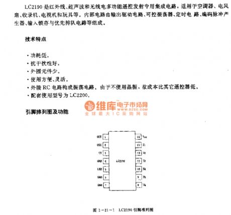

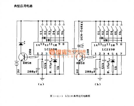
The LC2190 is designed as the infrared, ultrasonic and wireless remote control launch circuit that can be used in the air conditioner, electric fan, radio, TV and toy applications. The internal circuit is composed of the output driving circuit, the controllable oscillator, the timing cirucit, the coding pulse generator, the input latch circuit and the priority queuing circuit.etc.
Features
Low power consumption.Good anti-interference performance.Little external components.Easy to use.The external RC circuit forms the oscillating circuit. It does not need the crystal oscillator, so the cost of it is cheaper than other controllers.The matching model is LC2200.
(View)
View full Circuit Diagram | Comments | Reading(1736)
KEYLESS_LOCK
Published:2009/7/8 22:26:00 Author:May
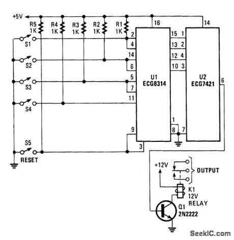
The circuit uses a four-bit latch(U1).What makes the circuit sequential is that the set input of the firstbit latch is tied to the reset of the second bit latch,and so forth.That ensures that any bit latched will be reset by the prevtous bit latch.The ECG8314 also has a master reset (pin 9)that is tiedto the first bit latch reset (pin 3),which provides an added measure of security for the lock.
The outputs of U1 are fed to a four-input AND gate(U2),then to Q1(used as switching transistor),which is used to drive relay K1. The EGC8314 has an enable low (pin) that can be used as a timing circuit,If that is desired. (View)
View full Circuit Diagram | Comments | Reading(895)
Circuit of Auto power off Nickel-cadmium Battery Charger
Published:2011/8/2 Author:Zoey | Keyword: Auto power off, Nickel-cadmium Battery, Charger

This circuit uses a simple timer. The four 500-mA Nickel-cadmium cells are connected in series. After charging for 15 hours in a constant current of 50mA, the circuit will cut off automatically, the charging process will be ceased. This circuit uses a 555 timer as a clock circuit, and it can produce the square wave in a period of 6s and use the wave to trigger IC2. IC2 will be connectedto be a divider of 8192:1. While charging, transistor T1 will conduct, forcing the relay RL1 to pick up. Light of LED indicates the formal process of charge. After the 555 be sent to IC2 and 8192 clock time pulses, pin 3 of IC2 will be in high level, T1 will stop working, RL1 will release, the circuit will stop charging. Pressing the switch S1, the relay will pick up automatically, and charging process will proceed until the scheduled time. (View)
View full Circuit Diagram | Comments | Reading(1829)
40_W_CM_TRANSCEIVER
Published:2009/7/8 22:24:00 Author:May
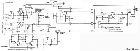
The unit consists of a direct conversion receiver and 1-W transmitter. The direct conversion receiver VFO is tuned just off frequency from the incoming signal. This difference in frequency produces a clean, strong, and solid audio tone signal. Detect the resonant frequency of the transmitter VFO by using the GDO as a field-strength meter.Because of the large capacitance in the Colpitts VFO, the tuning coil will have fewer turns than the mixer coil. Use the capacitance shown for the VFO gate to ground and to the coil. It will effect the fre-quency and output. You'll need 1.4-V rms on pin 2 of the mixer to get a good signal from the VFO. The 1000-Ω resistor and 0.01-μF capacitors act as an rf filter from the mixer output. (View)
View full Circuit Diagram | Comments | Reading(997)
A_D_divider
Published:2009/7/21 4:39:00 Author:Jessie

A/D divider (courtesy Analog Devices, Inc.). (View)
View full Circuit Diagram | Comments | Reading(777)
KS5410 (TV, video tape recorder and audio equipment) infrared remote control launch circuit
Published:2011/8/1 21:53:00 Author:TaoXi | Keyword: TV, video tape recorder, audio equipment, infrared, remote control, launch circuit
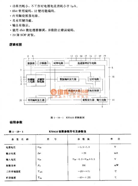
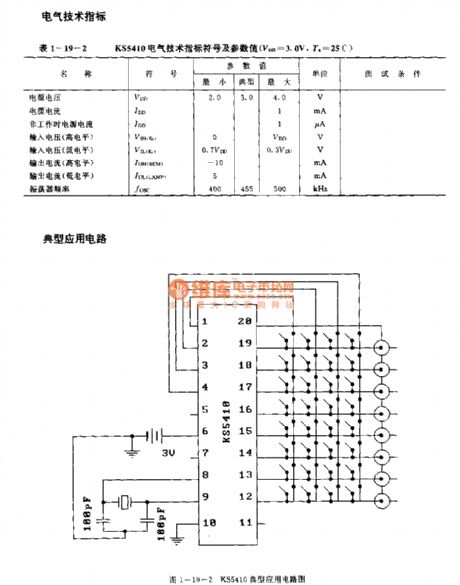
The KS5410 is designed as the infrared remote control launch circuit that can be used in the TV, video tape recorder and audio equipment applications. The internal circuit is composed of the oscillator, the frequency divider, the button input circuit, the multi-key suppression circuit, the common code generator, the data coding generator, the data register, the strobe pulse signal circuit, the clock circuit, the timing circuit, the system controller, the carrier frequency generator and the output current.
Features
The power voltage is low, the range is 2.0-4.0V.The transmission efficiency is high, the duty ratio is 1.8%.The power consumption is small, when it is not in the operating state, the power current consumption is smaller than 1uA.8-bit commonly used code, 32-button function code.It has the ceramic oscillating circuit.It has the double-button function.
(View)
View full Circuit Diagram | Comments | Reading(1447)
Difference_of_squares_circuit_using_an_AD534_multiplier_divider_chip
Published:2009/7/21 4:39:00 Author:Jessie

Difference of squares circuit using an AD534 multiplier/divider chip (courtesy Analog Devices, Inc.). (View)
View full Circuit Diagram | Comments | Reading(487)
ACTIVE_ANTENNA_WITH_GAIN
Published:2009/7/8 22:20:00 Author:May

The signal boostei,built around a few transistors and support components,offers an RF galn of about12 to 18 dB (from about 100 kHz to over 30 MHz).
The RF signal is direct-coupled from Q1’s Source terminal to the base of Q2,which is configured as avoltage amplifier. The output of Q2 is then direct-coupled to the base of Q3 (configured as an emitter-fallower amplifier).Transistor Q3 is used to match and isolate the gam stage from the receiver’s RF-inputcircuitry.
Inductor L1 is used to keep any power Source nolse from reaching the FET (Q1) and any value of RF choke from 0.5 to 2.5 mH will do.The value of R2 sets the Q2 bias at about 2V. If the voltage is less than 2V, Increase the value of R2 to 1.5 kΩ,To go below 100 kHz(to the bottom ofthe RF spectrum),increasethe value of C1 to 0.002 μF. The antenna is a short pull-up type (42″to 86″long). (View)
View full Circuit Diagram | Comments | Reading(675)
KS5803A/B (tape recorder, TV, video recorder and toy) infrared remote control launch circuit
Published:2011/8/1 22:01:00 Author:TaoXi | Keyword: tape recorder, TV, video recorder, toy, infrared, remote control, launch circuit


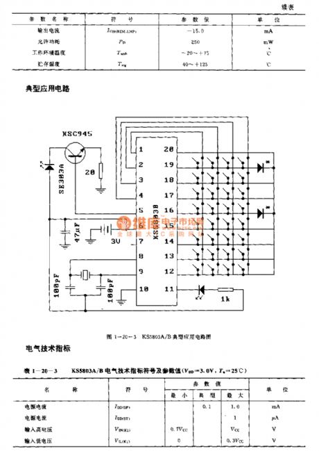
The KS5803A/B is designed as the infrared remote control launch circuit that can be used in the tape recorder, TV, video recorder and toy applications.
(View)
View full Circuit Diagram | Comments | Reading(1443)
HIGH_VOLTAGE_AC_SWITCHER
Published:2009/7/8 22:19:00 Author:May
A guide for selecting the component values would consist of the following steps:
· Choose C1 in a range of 0.05 to 1 μR The maximum value might be limited by the recharging time constant (RL + R1) C1 while the minimum value will be set by the minimum pulse width required to ensure SCR latching.· R2 is determined from peak gate current limits, if applicable, and minimum pulse width requirements.· Select a zener diode. A 25-V zener is a practical value, since this will meet the usual gate requirement of 20 V and 20 Ω. This diode will also eliminate spurious triggering because of voltage transients.· Photon coupler triggering is ideal for the SCR's driving inductive loads. By ensuring that the LASCR latches on, it can supply gate current to SCR1 until it stays on.· Component values for dc voltage are easily computed from the following formulae: EIN-VZR1 = — IG where: V =zener voltage P(R1) =IG·(EIN-VZ) P(ZENER) =IG·VZ (View)
View full Circuit Diagram | Comments | Reading(0)
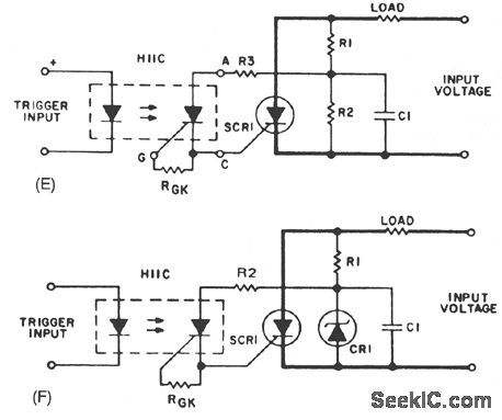
_HIGH_VOLTAGE_AC_SWITCHER
Published:2009/7/8 22:16:00 Author:May
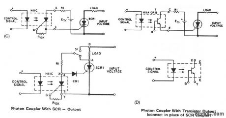
In Fig. 67-1C, R1 can be connected to Point A, which will remove the voltage from the coupler after SCR1 is triggered, or to Point B so that the coupler output will always be biased by input voltage. The former is preferred since it decreases the power dissipation in R1. A more practical form of SCR triggering is shown in Fig. 67-1F. Trigger energy is obtained from the anode supply and stored in C1. Coupler voltage is limited by the zener voltage. This approach permits switching of higher voltages than the blocking voltage capability of the output device of the photon coupler. To reduce the power losses in R1 and to obtain shorter time constants for charging C1, the zener diode is used instead of a resistor. (View)
View full Circuit Diagram | Comments | Reading(587)
DIGITAL_ENTRY_LOCK
Published:2009/7/8 22:15:00 Author:May

A keypad enters a four-digit access code, which is programmed via jumpers on a 24-pin plug-in header and socket. U1 is an LST220, which detects a four-digit sequential data input. When the correct data is entered into the keyboard, pin 13 of U1 goes high, which activates Q1 and K1. K1 drives an external electric lock solenoid, etc. (View)
View full Circuit Diagram | Comments | Reading(1570)
LM1812 (industrial control, communication and alarm equipment) ultrasonic remote control transmitting or receiving circuit
Published:2011/8/2 3:17:00 Author:TaoXi | Keyword: industrial control, communication, alarm equipment, ultrasonic, remote control, transmitting, receiving circuit


The LM1812 is designed as the ultrasonic remote control transmitting or receiving circuit that can be used in the industrial control, communication and alarm equipment applications. The internal circuit is composed of the oscillator, the detector, the integrator, the duty ratio limiter and the output circuit.
Features
The external LC components form the oscillating circuit, it does not need the crystal oscillator.The IC has the protection circuit.The measuring distance in the water is more than 30m, the measuring distance in the air is more than 6m.The peak value of the output power can be 12W.
(View)
View full Circuit Diagram | Comments | Reading(1801)
HIGH_VOLTAGE_AC_SWITCHER
Published:2009/7/8 22:13:00 Author:May
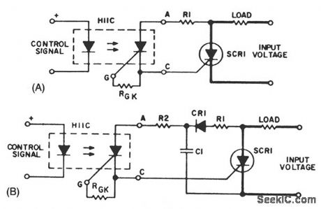
A basic circuit to trigger an SCR is shown in Fig. 67-1A. This circuit has the disadvantage that the blocking voltage of the photoncoupler output device determines the circuit-blocking voltage, irrespective of higher main SCR capability.
Adding capacitor C1 to the circuit, as shown in Fig. 67-1B, will reduce the dV/dt seen by the photon-coupler output device. The energy stored in C1, when discharged into the gate of SCR1, will improve the di/dt capability of the main SCR.
Using a separate power supply for the coupler adds flexibility to the trigger circuit; it removes the limitation of the blocking voltage capability of the photon-coupler output device. The flexibility adds cost and more than one power supply nftght be necessary for multiple SCRs if no common reference points are available. (View)
View full Circuit Diagram | Comments | Reading(767)
| Pages:933/2234 At 20921922923924925926927928929930931932933934935936937938939940Under 20 |
Circuit Categories
power supply circuit
Amplifier Circuit
Basic Circuit
LED and Light Circuit
Sensor Circuit
Signal Processing
Electrical Equipment Circuit
Control Circuit
Remote Control Circuit
A/D-D/A Converter Circuit
Audio Circuit
Measuring and Test Circuit
Communication Circuit
Computer-Related Circuit
555 Circuit
Automotive Circuit
Repairing Circuit