
Circuit Diagram
Index 940
Positive_switching_regulator5_volts_using_an_ECG915_or_ECG915D
Published:2009/7/20 20:49:00 Author:Jessie
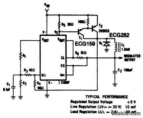
Positive switching regulator(5 volts) using an ECG915 or ECG915D. For a ±5% fixed output R1 is 1.15 ohms and R2 is 4.99 ohms. For metal can applications where Vz is required connect a 6.2-volt zener in series with the regulated output (courtesy GTE Sylvania Incorporated). (View)
View full Circuit Diagram | Comments | Reading(562)
IRON_LUNG_AIR_INTAKE_CONTROL
Published:2009/7/20 21:03:00 Author:Jessie

Air exhaled by patient is sampled and analyzed for carbon dioxide concentration by commercial infrared analyzer that provides electrical output proportional to amount of carbon dioxide. Analyzer output charges C2 to level dependent on carbon dioxide concentration. Comparison circuit controls relays K2 and K3 so iron lung bleeder valve keeps concentration within preset limits. V5, V6, and K2 establish upper limitV7, other half of V6, and K3 establish lower limit.-Control Regulates Iron Lung, Electronics, 31:41, p 108. (View)
View full Circuit Diagram | Comments | Reading(921)
Two_component_precision_current_limiter_1
Published:2009/7/20 21:03:00 Author:Jessie
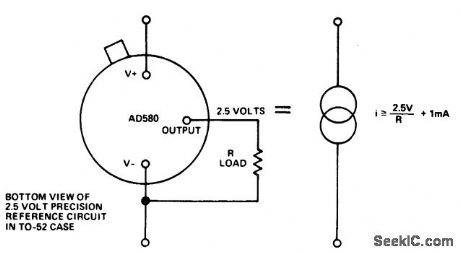
Two-component precision current limiter (courtesy Analog Devices, Inc.). (View)
View full Circuit Diagram | Comments | Reading(513)
EEG_TELEMETER
Published:2009/7/20 21:01:00 Author:Jessie

Amplifier, modulator, and oscillator produce 37.7-Mc signals frequency-modulated by scalp voltages of epileptics. Radiated signal may be picked up by antenna of receiver at distances up to 40 feet from patient in observation room.-C. L. Yeager and J. Henderson, Jr., Unit Telemeters Scalp Voltages, Electronics, 31:29, p 86. (View)
View full Circuit Diagram | Comments | Reading(816)
EMITTER_FEEDBACK_PEAKING_GIVES_100_MC_BANDWIDTH
Published:2009/7/20 21:01:00 Author:Jessie


Four identical AF102 stages amplify pulse output of delta modulator in tv waveguide link.-C. Kramer and J. C. Balder, Delta-Modulated Television Waveguide Link, Electronics, 36:31, p 50-52.
(View)
View full Circuit Diagram | Comments | Reading(632)
ESSURE_SENSITIVE_RESISTOR_CONTROLSARTIFICIAL_HAND
Published:2009/7/20 21:00:00 Author:Jessie

Control binary Q6-07 is triggered on through diode AAZ18 and reset by Q8 whose conduction threshold is determined by R1. Settings of R1, R2, and RC control closing of artificial hand and strength of grip. Servo amplifier drives motor in hand and follow-up potentiometer.-G. W.Horn, Muscle Voltage Moves Artificial Hand, Electronics, 36:41, p 34-36. (View)
View full Circuit Diagram | Comments | Reading(1983)
FOUR_TRANSISTOR_T_U_N_E_R
Published:2009/7/20 21:00:00 Author:Jessie

Diffused-base mesa transistors permit design of tv tuners with noise performance equal to that of tube tuners. Article gives complete design procedure for r-f amplifier, mixer, and oscillator stages.-H. F. Cooke, Designing Tv Tuners with Mesa Transistors, Electronics, 33:15, p 64-69. (View)
View full Circuit Diagram | Comments | Reading(1002)
Precision_voltage_controlled_current_source_using_an_op_amp_and_two_FETs
Published:2009/7/20 21:00:00 Author:Jessie
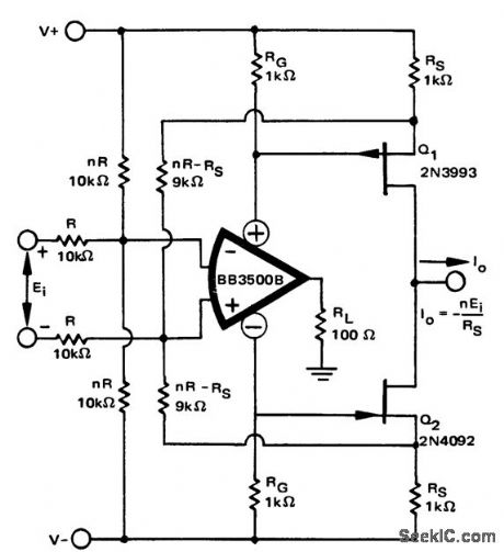
Precision voltage-controlled current source using an op amp and two FETs (courtesy Burr-Brown Research Corporation). (View)
View full Circuit Diagram | Comments | Reading(2038)
Adjustable_output_regulators_for_5_6_12_15_or_24_volts
Published:2009/7/20 20:59:00 Author:Jessie
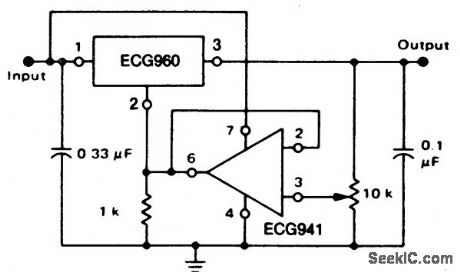
Adjustable output regulators for 5, 6, 12, 15, or 24 volts. The input capacitor is valued at 0.33 pF if Mylar or tantalum; if aluminum, it should be 1.0 pF or larger. Although the circuit shown is for a 7-volt output, voltages of 8, 14, 17, or 26 volts can be obtained by substituting ECG962, ECG966, ECG968 or ECG972, respectively, for the ECG960. These devices are three-terminal 1-ampere devices. The minimum voltage obtainable is 2 volts greater than the regulator voltage (courtesy GTE Sylvania Incorporated). (View)
View full Circuit Diagram | Comments | Reading(563)
CCTV_10_MC_CARRIER_TRANSMITTER_TERMINAL
Published:2009/7/20 20:59:00 Author:Jessie

Uses single tetrode transistor in oscillator to feed four-diode balanced modulator. Peak level of modulator output is 4 db below 1 mw.-L. G. Schimpf, Carrier Transmission for Closed-Circuit Television, Electronics, 32:24, p 66-68. (View)
View full Circuit Diagram | Comments | Reading(623)
ANESTHESIA_CONTROL
Published:2009/7/20 20:59:00 Author:Jessie

Drives anesthetic pump servomotor in response to signals from electroencephalograph that continuously monitors border of wakefulness of patient undergoing surgical operation Anesthetic is supplied at fixed level, proportion to cortical activity of brain,-How Electronics Controls Depth of Anesthesia Electronics, 32;5,p 43-45. (View)
View full Circuit Diagram | Comments | Reading(783)
CCTV_REPEATER_POWER_SUPPLY
Published:2009/7/20 20:59:00 Author:Jessie

CCTV REPEATER POWER SUPPLY-Operates from 24.v battery at transmitting terminal. C1 isolates battery voltage from terminal equipment, and L1 prevents shorting of signal. Two 7-v zener diodes in series serve as voltage regulators.-L. G. Schimpf, Carrier Transmission for Closed-Circuit Television, Electronics, 32:24, p 66-68.
(View)
View full Circuit Diagram | Comments | Reading(1408)
HORIZONTAL_DEFLECTION_1
Published:2009/7/20 20:58:00 Author:Jessie

Two-transistor circuit provides high ratio of reverse to for. ward base drive. Oscillator current is 0.12 amp, output-stage current 0.72 amp, und push-pull yoke current is 11 amp.-M. Fischman, Transistorized Horizontal Deflection for Television, Electronics, 32:33, p 60-63. (View)
View full Circuit Diagram | Comments | Reading(1144)
SAMPLE_READOUT_AMPLIFIER
Published:2009/7/20 21:13:00 Author:Jessie
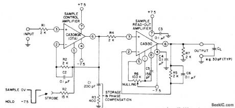
RCA CA3080A oporational trans conductance amplifier feeds CA3130 to give amplification of sampled signal. Input voltage is sampled for duration of strobe pulse and held for readout.- Linear Integrated Circuits and MOS/FET's, RCA Solid State Division,Somerville,NJ,1977,P165-170. (View)
View full Circuit Diagram | Comments | Reading(653)
HEART_PACER
Published:2009/7/20 21:12:00 Author:Jessie

Supplies pulses that drive heart at desired rate. Output is connected to heart muscles by small wires. Frequency of relaxation oscillator is controlled, between 50, and 200 ppm, by R2.-L. D. Trump and R. L. Skinner, Simple Heart Pacer is Highly Reliable, Electronics, 32:39, p 92-93. (View)
View full Circuit Diagram | Comments | Reading(710)
MUSCIE_SIGNAL_AMPLIFIER
Published:2009/7/20 21:12:00 Author:Jessie

Differential input amplifier Q1-02 accepts myoelectric signals of 10 to 1,000 microvolts from stump muscles of amputee. Stagger-tuned interstage trans-formers for Q3-Q4 give bandwidth of 100to 1,000 cps +or main amplifier that drives integrating detector Q5 that operates relay to control servomotor for artificial hand.-G. W. Horn, Muscle Voltage Moves Artificial Hand, Electronics, 36:41, p 34-36. (View)
View full Circuit Diagram | Comments | Reading(1502)
TWO_SLEW_RATES
Published:2009/7/20 21:11:00 Author:Jessie

Cost of sample-and-hold circuits is reduced by using high slew rate only during sample period. Programmable μA776 opamp permits switching from high rate requiring 50-nA input bias current to holding amplifier mode requiring only 750-pA input bias current. Output level is held constant within 1% for about 2 s, making circuit ideal for digital readouts.-M. K. Vander Kooi, Low Cost Sample-and-Hold Circuit, EDN/EEE Magazine, Nov.1,1971, p 46. (View)
View full Circuit Diagram | Comments | Reading(1284)
HEART_RATE_REGULATOR
Published:2009/7/20 21:10:00 Author:Jessie

Senses arterial pressure and differentiates pressure signal to eliminate mean pressure and produce required sharp spike at beginning of each pressure pulse. Spikes ore used to control regulator that delivers pulses to vagus nerve that controls muscles of heart.-R. L. Skinner, D. X. Gehmlich, and F. W. Longson, Blood Pressure and Heart Rate Regulator, Electronics, 32:1, p 38-41. (View)
View full Circuit Diagram | Comments | Reading(787)
Positive_floating_regulator_50_volts_using_an_ECG915_or_ECG915D_IC
Published:2009/7/20 21:09:00 Author:Jessie
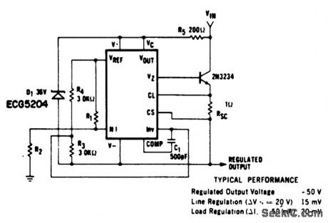
Positive floating regulator (50 volts) using an ECG915 or ECG915D IC. For a ±5% fixed output R1 is 3.57 ohms and R2 is 48.7 ohms. For metal can applications where Vz is required, an external 6.2-volt zener should be connected in series with the regulated output (courtesy GTE Sylvania Incorporated). (View)
View full Circuit Diagram | Comments | Reading(637)
Current_comparator_with_low_input_impedance_using_an_AD7570_10_bit_A_D_converter
Published:2009/7/20 21:09:00 Author:Jessie
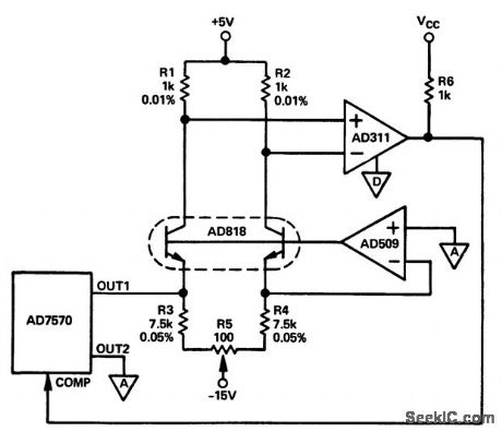
Current comparator with low input impedance using an AD7570 10-bit A/D converter (courtesy Analog Devices, Inc.). (View)
View full Circuit Diagram | Comments | Reading(614)
| Pages:940/2234 At 20921922923924925926927928929930931932933934935936937938939940Under 20 |
Circuit Categories
power supply circuit
Amplifier Circuit
Basic Circuit
LED and Light Circuit
Sensor Circuit
Signal Processing
Electrical Equipment Circuit
Control Circuit
Remote Control Circuit
A/D-D/A Converter Circuit
Audio Circuit
Measuring and Test Circuit
Communication Circuit
Computer-Related Circuit
555 Circuit
Automotive Circuit
Repairing Circuit