
Circuit Diagram
Index 926
VOLTAGE_TUNED_HARTLEY_JFET_VFO
Published:2009/7/21 2:15:00 Author:Jessie

This voltage-tuned JFET Hartley oscillator can be made to sweep its entire frequency range by applying a sawtooth waveform that rises from 0 to 12 V to the Vt input. In this circuit, a varactor is used for the tuning element instead of an air-core inductor. The frequency range is around 5 MHz. (View)
View full Circuit Diagram | Comments | Reading(680)
VARIABLE_VNEN_BRIDGE_OSCILLATOR
Published:2009/7/9 1:30:00 Author:May


A Wien-bridge oscillator can be made variable by using two frequency-determining parts that are var-ied simultaneously at high tracking accuracy. High-quality tracking potentiometers or variable capacitors are, however, expensive and difficult to obtain. To avoid having to use such a component, this oscillator was designed to operate with a single potentiometer. The output frequency, f0,is calculated from:
With preset P2 you can adjust the overall amplification so that the output signal has a easonably stable amplitude, 3.5 VPP max., over the entire frequency range. The stated components allow the frequency to be adjusted between 350 Hz and 3.5 kHz. (View)
View full Circuit Diagram | Comments | Reading(1550)
Keling ZTP-63A Type Dual Function Disinfector Cabinet Principle And Repairing Circuit
Published:2011/8/3 9:11:00 Author:Robert | Keyword: Keling, Dual, Function, Disinfector Cabinet, Principle, Repairing

The Keling ZTP-63A type dual function tableware disinfector cabinet is dual door and dual room structure. It has many advantages such as thorough disinfection, no pollution, sage and stable, easy to use, and so on. This artical intruduces this disinfector cabinet's working principle and common faults' repairing methods for repairing reference.The working principle is intruduced below.This disinfector cabinet's circuit is drawn and shown in the picture. The full circuit is made up of three parts which are high-temperature disinfector circuit, temperature-keeping circuit and ozone disinfector circuit. In the high-temperature disinfector circuit, when it is connected to the power and the user presses the disinfector switch SB1, the relay K would get electricity and become closed. And the normally open contactor K1, K2 are closed to be connected. Then the working indication lamp (red) HL1 would light. (View)
View full Circuit Diagram | Comments | Reading(1810)
SIMPLE_RIPPLE_SUPPRESSOR
Published:2009/7/9 1:29:00 Author:May
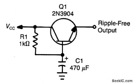


This circuit, at times called a capacitcance multiplier, is useful for suppression of power-supply rip-ple. C1 provides filtering that is equal to a capacitor of (B+1) C1, where B = dc current gain of Q1 (typi-cally > 50). (View)
View full Circuit Diagram | Comments | Reading(1933)
BUFFER_AMPLIFIER_WITH_MODULATOR
Published:2009/7/9 1:28:00 Author:May
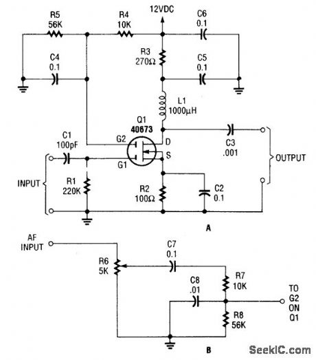
A 40673 MOSFET is used as a wideband buffer amplifter (to 20 MHz). If desired, the amplifier can be modulated, considering that the gate 2 voltage of a MOSFET can be used to vary the gain of the stage. (View)
View full Circuit Diagram | Comments | Reading(914)
MODIFIED_HARTLEY_OSCILLATOR
Published:2009/7/21 2:15:00 Author:Jessie

A. F. Lampkin, in 1939, showed that a high-C Hartley oscillator (as typically used in the once popular ECO VFO) could be improved by a factor of about 10 times simply by tapping the grid (gate or base) connection down the coil. (View)
View full Circuit Diagram | Comments | Reading(0)
WIDEBAND_AMPLIFIER
Published:2009/7/9 1:26:00 Author:May

Using a Signetics NE5205, this circuit gives about + 16-dB gain from LF to 600 MHz. The π mini-mizes load impedance and source-impedance variations and aids stability. (View)
View full Circuit Diagram | Comments | Reading(1922)
Transducer_linearization_circuit_using_the_433_multiplier_divider_chip
Published:2009/7/21 2:16:00 Author:Jessie
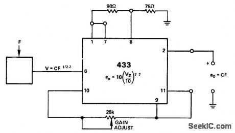
Transducer linearization circuit using the 433 multiplier/divider chip (courtesy Analog Devices, Inc.). (View)
View full Circuit Diagram | Comments | Reading(509)
10_PPM_℃
Published:2009/7/8 23:17:00 Author:May

Connections shown convert LM723CH regulator into precision power reference having excellent long-term stability and temperature stability. LM399H replaces internal reference of LM723 with low-noise 6.9 V to give desired performance over temperature range from +15 to +65℃.-B. Welling, High-Stability Power Supply Uses 723 Regulator, EDNMaga-zine, Jan. 20, 1978, p 114 and 116. (View)
View full Circuit Diagram | Comments | Reading(3092)
5AAT__5TO__15_V
Published:2009/7/8 23:17:00 Author:May
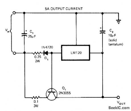
Use of 2N3055 pass transistor boosts current output of LM120 regulator IC. Minimum differential between input and output voltages is typically 2.5 V, so supply voltage must be 2.5 V higher than preset output voltage of regulator chosen from National LM120 series.-C. T. Nelson, Power Distribution and Regulation Can Be Simple, Cheap and Rugged, EDN Magazine, Feb, 20, 1973, p 52-58. (View)
View full Circuit Diagram | Comments | Reading(683)
NE602_HARTLEY_OSCILLATOR
Published:2009/7/21 2:16:00 Author:Jessie

In this Hartley VFO, feedback is provided via a tap on the inductor. (View)
View full Circuit Diagram | Comments | Reading(700)
CONVERTING_TO_DUAL_SUPPLY
Published:2009/7/8 23:16:00 Author:May
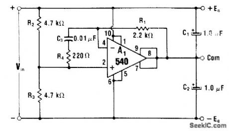
With equal values for R2 and R3, input of 30 V is converted to ±15 V at output. If desired, R2 and R3 can be scaled for unequal voltage drops. Circuit uses 540 power IC having 100-mA rating for each out-put, for handling load imbalances up to 100 mA.-W. G. Jung, IC Op-Amp Cookbook, Howard W. Sams, Indianapolis, IN, 1974, p 170-171. (View)
View full Circuit Diagram | Comments | Reading(601)
High-Voltage Isolating Current Detection Circuit (ISO212 And OPA27)
Published:2011/8/3 9:39:00 Author:Robert | Keyword: High-Voltage, Isolating, Current, Detection
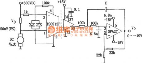
In the circuit which has hundreds of volts voltage, if you want to detect the current you must solve the voltage isolating problem. One kind of practical circuit that can meet the requirements above is shown in the picture. The circuit uses a isolating amplifier ISO212P. This element is dual-port isolating miniaturization IC. The motor shown in the picture is a DC motor with 500V power supply. It is added a little resistor in series with the motor's power supply loop circuit for current detection. The resistor's value's selection should satisfy that it could get the maximum voltage signal of 50mV at the maximum current. Because the signal got from the sampling resistor would be added into the isolating amplifier ISO212P's pin 3 by the the out-phase input method, the amplifier's in-phase input port (pin 1) would connect to the ground. It should be noted that the ISO212P's input ground (pin 2) and the motor's power supply's ground should be connected, which means they are not common in ground. (View)
View full Circuit Diagram | Comments | Reading(627)
OVERLOAD_PROTECTION
Published:2009/7/8 23:15:00 Author:May

When critical current is exceeded, SCR1 condtlcts and reduces base-ground voltage of Q1 cutting it off. Load current then drops to very low value, and Q1 is protected. Operation is restored by turning off current supply to power transformer after clearing short-circuit condition.-R. Phelps, Jr., Protective Circuits for Transistor Power Supplies, CQ March 1973, p 44-48 and 92. (View)
View full Circuit Diagram | Comments | Reading(0)
3_watt_differential_output_power_amplifier_using_two_MC1554s
Published:2009/7/21 2:17:00 Author:Jessie

3-watt differential output power amplifier using two MCl554s (courtesy Motorola Semiconductor Products Inc.). (View)
View full Circuit Diagram | Comments | Reading(539)
HARTLEY_VFO_WITH_BUFFER_AMPLIFIER
Published:2009/7/21 2:18:00 Author:Jessie

The figure shows a Hartley oscillator with buffer amplifier. This circuit can be tuned via C1, or if C1 is removed and the varactor network is connected to point A, a tuning voltage can be used instead. For best stability, L1 can be replaced with an air-core unit. Frequency range is 2 to 5 MHz, but the circuit can operate 1 to 10 MHz with suitable values of L1, C2, C3, C4, and C5. (View)
View full Circuit Diagram | Comments | Reading(1305)
TREMOLO_3
Published:2009/7/8 23:15:00 Author:May

This simple circuit can color the sound cormng from your audio system. Clocking for the circuit is provided by an oscillator built from one quarter of a 4093 quad NAND Schmitt trigger. With the component values shown, it will run at about 5 Hz. The clock frequency is fed to the gain control, pin 8, of an LM386 amplifier. Tremolo is produced by varying the amplifier gain. A trimmer potentiometer can be put in series with R1, to easily experiment with different rates. To experiment, make R1 about 100-KΩ and use a 1-MΩ trimmer. That allows frequen-cies from about 2 to 20 Hz to pass. Resistor R2 is the depth control. It controls the degree of tremolo. To adjust, put a trimmer in series with R2. Make R2 a 5-KΩ unit and use a 50-KΩ trimmen Since the tremolo clock uses the gain-control pin of the amplifier, change the value of capacitor C4 in order to change the gain of the amplifter. Make C4 larger to increase the gain or smaller to decrease it. But. don't go any lower than 0.1 μF because you'll be cutting into the bottom-end frequency response. (View)
View full Circuit Diagram | Comments | Reading(823)
Summing_scaling_amplifier_using_an_MC1552G
Published:2009/7/21 2:19:00 Author:Jessie
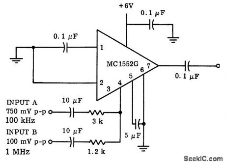
Summing/scaling amplifier using an MC1552G. Scaling considerations are accomplished by adjustment of the input resistors (courtesy Motorola Semiconductor Products Inc.). (View)
View full Circuit Diagram | Comments | Reading(481)
25_V_AT_10_A_FOR_LAB
Published:2009/7/8 23:14:00 Author:May

Circuit uses no large output capacitors yet has good response as constant-voltage or constant-current source.LM395 units (7 in parallel) act as current-limited thermally limited high-gain power transistor.Mount all on same heatsink for good current sharing, since 300 W will be dissipated under worst-case conditions. Only two control opamps are needed, oneforvoltage control and one for current control.-R. C. Dobkin, General-Purpose Power Supply Furnishes 10A and 25V, EDNMagazine, March 5, 1975, p 70. (View)
View full Circuit Diagram | Comments | Reading(646)
_15V_WITH_μA723
Published:2009/7/8 23:13:00 Author:May
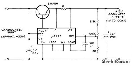
Series power transistor and Fairchild IC voltage regulator provide up to 100 mA. Article covers troubleshooting and repair of all types of regulators.-H. Olson, Power-Supply Servicing, Ham Fladio, Nov.1976, p 44-50. (View)
View full Circuit Diagram | Comments | Reading(692)
| Pages:926/2234 At 20921922923924925926927928929930931932933934935936937938939940Under 20 |
Circuit Categories
power supply circuit
Amplifier Circuit
Basic Circuit
LED and Light Circuit
Sensor Circuit
Signal Processing
Electrical Equipment Circuit
Control Circuit
Remote Control Circuit
A/D-D/A Converter Circuit
Audio Circuit
Measuring and Test Circuit
Communication Circuit
Computer-Related Circuit
555 Circuit
Automotive Circuit
Repairing Circuit