
Circuit Diagram
Index 938
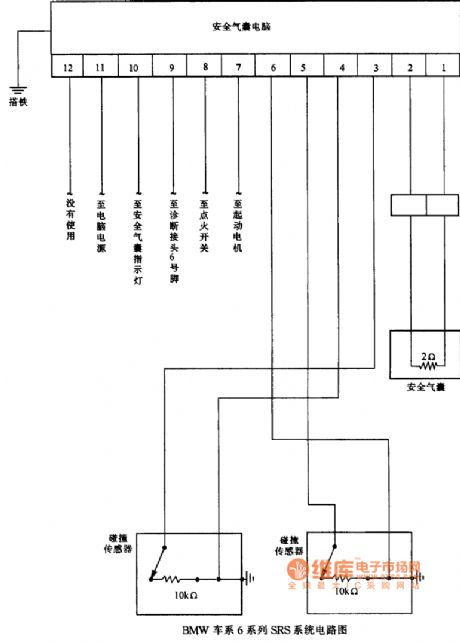
BMW 6 series of SRS system circuit diagram
Published:2011/8/2 22:38:00 Author:Ecco | Keyword: BMW , 6 series , SRS system
View full Circuit Diagram | Comments | Reading(564)
THERMISTOR_CONTROLLED_TIMER_
Published:2009/7/8 5:49:00 Author:May
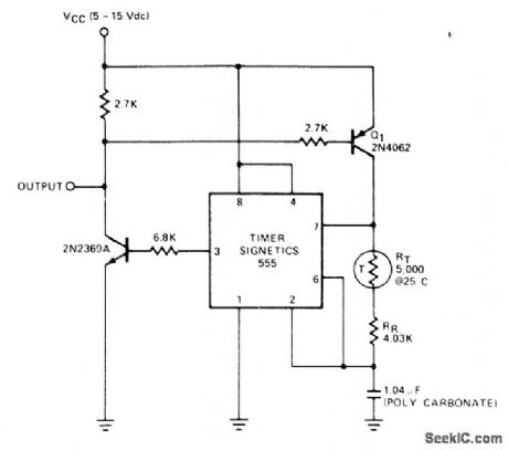


Thermistor and two transistors in charging network of 555 timer give outputfrequency that varies with temperature over 78°F range with accuracy of ±1 Hz. — Signetics Analog Data Manual, Signetics, Sunnyvale, CA, 1.977, p 731.
(View)
View full Circuit Diagram | Comments | Reading(1243)
0_15_MHz_WITH_100_dB_CMR_
Published:2009/7/8 5:35:00 Author:May

Differential inputs are applied to Optical Electronics 9715 opamp through 9714 voltage followers. Currentbooster using 9810 opamp raises load current to ±100 mA. Complete amplifier has very high differential and common-mode input impedance. Common-mode rejection can be trimmed to greater than 100 dB at 1 kHz for unity gain.Gain is determined by value of resistor RG connected between points A and B and is equal to(2R2/R1)(1 + 2R2/RG). Settling time is 500 ns.Accuracy is maintained from -550C to +85 0C-''Instrumentation Ampliffer, Optical Electronics, Tucson, AZ, Application Tip 10240. (View)
View full Circuit Diagram | Comments | Reading(748)
01℃_PRECISION
Published:2009/7/8 5:32:00 Author:May

Temperature sensor is LM113 diode in probe, with sections A1 and A2 of LM324 quad opamp maintaining constant current to diode to ensure that voltage changes across diode are direct result of temperature.4.5-V output of A1 is reference point for other opamps. Changes in output voltage of diodeare reflected in output of A4 through buffer A3. Calibration involves adjusting R6 for zero output voltage at low end of temperature range,then adjusting R10 for full-scale or other convenient reading at desired upper temperature limit. Use 1-mA meter movement.-Y. Nezer, Accurate Thermometer Uses Single Quad Op Amp, Electronics, May 26, 1977, p 126. (View)
View full Circuit Diagram | Comments | Reading(1901)
TEMPERATURE_TO_FREQUENCY_CONVERT_ER
Published:2009/7/8 5:29:00 Author:May
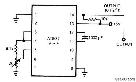
Temperature sensor on chip of AD537 voltage-to-frequency converter IC minimizes number of external parts needed. Output frequency changes 10 Hz for each degree (kelvin or Celsius) change in temperature.-J. Williams, De-signer's Guide to: Temperature Measurement, EDNMagazine, May 20, 1977, p 71-77. (View)
View full Circuit Diagram | Comments | Reading(1019)
THERMOCOUPLE_AMPLIFIER
Published:2009/7/8 5:28:00 Author:May
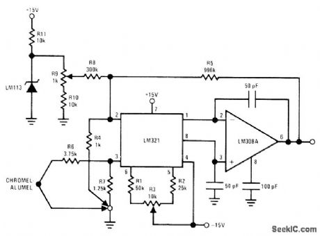
Combination of LM321 preamp and LM30SA opamp forms precision low-drift amplifier that includes compen-sat;on for ambient temperature variations.LM113 zener provides temperature-stable reference for offsetting output to read thermocouple temperature directly in degrees C. R4, R6, and R7 should be wirewound.-R. C. Dobkin, Versatile IC Preamp Makes Thermocouple Am-plifier with Cold Junction Compensation, Na-tional Semiconductor, Santa Clara, CA, 1973, LB-24. (View)
View full Circuit Diagram | Comments | Reading(0)
PROXIMITY_DETECTOR
Published:2009/7/8 5:28:00 Author:May

Output changes from high (9 V) to low (0 V) when conducting object moves within1cm from open end of 150-turn coil L (No.34 enamel) mounted in half of Fer-roxcube 1811-PL00-3B7 core set. Can be used as contactless limit switch or tachometer pickup.Q1-Q 4are CM0S MOSFETs in CD4007A package.Q1 and pickup coil form 100-kHz oscillator Diodes develop DC voltage proportional to peak-to-peak value of oscillator signal, for application to Schmitt trigger Q2-Q4. Conductive object near coil absorbs energy from magnetic field, lowering oscillator amplitude and turning Schmitt trigger off. 10K pot adjusts sensitivity.Circuit drives CM0S logic directly. For TTL drive, use buffer.-M. L. Fichtenbaum, Inductive Proximity Detector Uses Little Power, Electronics, Jan. 22, 1976, p 112. (View)
View full Circuit Diagram | Comments | Reading(0)
WIND_SPEED
Published:2009/7/8 5:21:00 Author:May

Developed to give magnitude of wind velocity over wide range of values when its two measured vectors are' expressed as voltages. Output is in Iogarithmig form for easy adaptation to data processorg. N-S and E-W veetor voltages from straitgage sensors ate converted to normalized values \/X and VYwhich are squared by MC1495L four-quadrant transconductance multipliers. Output currents are then summgct, and HA2705 opamp is used as differential current-to-voltage converterto obtain Vss as sum-of-squares ofVX and VY. Range covered is 1-100 mph. Article covers operation of circuit in detail.-J. A. Connolly and M.B.Lundberg.Analog Multipliers Determine True Wind Speed, EDN Magazine, April 20, 1974, p 69-72. (View)
View full Circuit Diagram | Comments | Reading(1108)
HEAT_ENERGY_INTEGRATOR
Published:2009/7/8 5:19:00 Author:May


Pulses of heat energy applied to solder preforms by tips of pulsed soldering machine are metered by integrate/hold-to-indicate circuit using thermocouple as input sensor. Temperature derived from area under time/temperature curve is indicated momentarily on output meter, as guide for operator when size of solder preform is changed.Article describes operation of circuit in detail and gives timing diagram.—C Brogado,Heat-Energy Pulse Measured and Displayed,EDN Magazine,Sept,15,1970,p 61-62. (View)
View full Circuit Diagram | Comments | Reading(821)
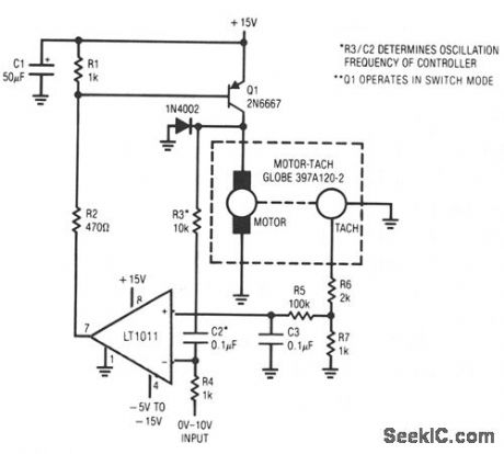
HIGH_EFFICIENCY_MOTOR_SPEED_CONTROLLER
Published:2009/7/8 5:17:00 Author:May
View full Circuit Diagram | Comments | Reading(692)
TEMPERATURE_TRANSDUCER_INTERFACE
Published:2009/7/8 5:17:00 Author:May

Output of National LX5600 temperature-sensing transducer is inverted, level-shifted, and given extra voltage gain of 4 to give required output of0 to +5 V for telemetry system or instrumentation recorder. Q1 furnishes constant current to thermometer, and Q2 provides inverting function. Resulting output signal is reinverted by LM201A opamp connected through zero-adjust divider to pin 3 which provides voltage reference.-P. Lefferts, A New Interfacing Concept; the Monolithic Temperature Transducer, National Semiconductor, Santa Clara, CA, 1975, AN-132, p 3. (View)
View full Circuit Diagram | Comments | Reading(666)
STEPPING_MOTOR_DRIVE
Published:2009/7/8 5:16:00 Author:May

The circuit shown in Fig. 62-15A is designed to drive a 15-V, two-phase, bipolar stepping motor, providing a bidirectional single level voltage across each winding at currents of up to 9.6 A. The circuit consists of two identical transistor bridge stages employing complementary npn and pnp devices.The transistor conduction sequence is determined by external control logic, and the circuit will interface directly with standard TTL, suitable controllogic system is illustrated in Fig.62-15B.
(View)
View full Circuit Diagram | Comments | Reading(859)
IC_FOR_DIFFERENTIAL_THERMOCOUPLE
Published:2009/7/8 5:16:00 Author:May


Amount of heat sensed by differential thermo-couple is proportional to voltage between pins 2 and a of CA3094A programmable power switch/amplifier. Input swing of ±26 mV gives single-ended output current range of ±8.35 mA.-E. M. Noll, Linear IC Principles, Experiments, and Projects, Howard VV. Sams, lndi-anapolis, IN, 1974, p 314.
(View)
View full Circuit Diagram | Comments | Reading(636)
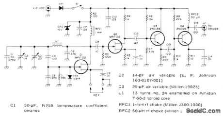
25_W_AIRCRAFR_AM_TRANSMΠTER
Published:2009/7/8 5:15:00 Author:May
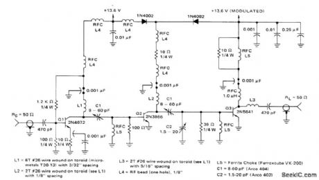
Oper-atesfrom 13.6-V supply,covers frequency rangeof 118-136 MHz without tuning,and has 50-ohm input and output terminations. Only three transistor stages are required. Diodes limit downward modulation to Q2. Upward modu-lation is 95%. Supply drain is 345 mA.- A 13-W Broadband AM Aircraft Transmitter, Moto-rola, Phoenix, AZ, 1974, AN-507, p 5. (View)
View full Circuit Diagram | Comments | Reading(1235)
_PWM_MOTOR_CONTROLLER
Published:2009/7/8 5:14:00 Author:May
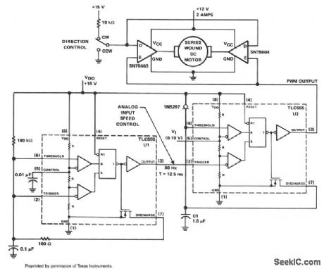
The PWM controller uses complementary half-H peripheral drivers SN75603 and SN75604, with totem-pole outputs rated at 40 V and 2.0 A. These drivers effectively place the motor in a full-bridge configuration, which has the ability to provide bidirectional control.
Timer U1 operates in the astable mode at a frequency of 80 Hz. The 100-Ω discharge resistor results in an 8-μs trigger pulse which is coupled to the trigger input of timer U2. Timer U2 serves as the PWM generator. Capacitor C1 is charged linearly with a constant current of 1 mA from the 1N5297, which is an FET current-regulator diode.
Motor speed is controlled by feeding a dc voltage of 0 to 10 V to control input pin 5 of U2. As the control voltage increases, the width of the output pulse pin 3 also increases. These pulses control the on/off time of the two motor drivers. The trigger pulse width of timer U1 limits the minimum possible duty cycle from U2. (View)
View full Circuit Diagram | Comments | Reading(1533)
107_MHz_LIMITING_AMPLIFIER
Published:2009/7/8 5:12:00 Author:May
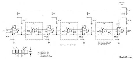
Uses SignetIcs NE510 transistor arrays in common-collector common-base configuration as IF strip for commercial FM broadcast receivel, Bandwidth is 300 kHz, achieved by ad justing transformers for 600-kHz bandwidth and using dual cup-core transformers originally designed for tubes.Windings were changed to give critical coupling Full limitingis provided by circuit with input voltage of 70 μVRMS.-''Signetics Analog Data Manual,″ Signetics Sunnyvale,CA,1977,p 747-748. (View)
View full Circuit Diagram | Comments | Reading(623)
_SPEED_CONTEOLLED_REVERSIBLE_DC_MOTOR_VRIVE
Published:2009/7/8 5:12:00 Author:May

The figure illustrates a reversible dc motor drive application with adjustable speed control. The D inputs for these drivers are complementary and can be tied together and driven from the same logic control for bidirectional motor drive. The enables are tied together and driven by a pulse-width-modulated generator providing on duty cycles of 10 to 90% for speed control. A separate enable control is provided through an SN7409 logic gate. See the truth table for this motor controller application.
Definitions for the terms used in the truth table are as follows:
EN EnableDC Direction controlSP.C Speed controlA Direction of current-right to leftB Direction of current-left to rightH Logic 1 voltage levelL Logic 0 voltage levelN Speed control set for narrow pulse width Speed control set for wide pulse widthX Irrelevant (View)
View full Circuit Diagram | Comments | Reading(1970)
500_mW_ON_180_kHz
Published:2009/7/8 5:11:00 Author:May
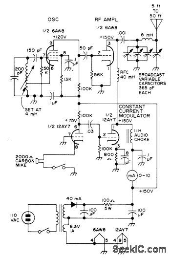
Meets FCC requirement for amateur radio operation in 160-190 kHz band with 1-W maximum plate input power and antenna up to 50 feet long including lead-in.Working range is about 1 mile. Uses electron-coupled oscillator to minimize frequency shift during modulation. RF amplifier is self-biased.40-mH choke in amplifier plate circuit is nearly self-resonant to 180 kHz.-C. Landahl, QRP on 180 kHz, 73 Magazine, May 1973, p 93-95. (View)
View full Circuit Diagram | Comments | Reading(1259)
300_W_LINEAR_SOLID_STATE
Published:2009/7/8 5:08:00 Author:May


Class A circuit using two MRF428A transistors is emitter-bal-lasted to ensure even current-sharing. Requires separate 0.5-1V regulated bias voltage source, circuit for which is given in article along with design procedure for amplifier. Second part of article (May 1976, p 28-30) tells how to combine four 300-W amplifiers to get 1-kW output for 1.8-30 MHz.-H. O. Granberg, One KW—Solid-State Style, QST, April 1976, p 11-14. (View)
View full Circuit Diagram | Comments | Reading(717)
TEMPERATURE_TO_FR_EOUENCY_CONVERT_ER
Published:2009/7/8 5:08:00 Author:May
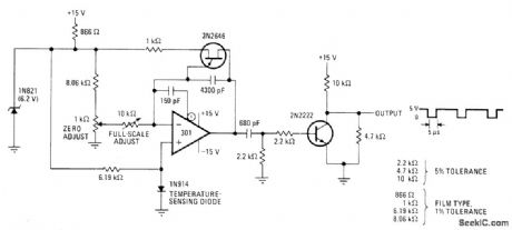
Frequency of relaxation oscillator varies linearly with temperature-dependent voltage across 1N914 diode sensor, with range of 0-1000 Hz for 0-100°C. Frequency meter at output shows temperature directly with accuracy of±0.3°C. Opamp is used as integrator, With 1N821 temperature-compensated diode providing voltage reference that determines firingpoint of UJT Circuit functions as voltage-to-frequency converter, Calibrate at 100°C and 0°C,repeating until adjustments cease to interact,Output frequency is then to times Celsius temperature.-J. Williams and T. Durgavich, Direct-Reading Converter Yields Temperature, Ele-tronics, April3, 1975, p 101 and 103; reprinted in Circuits for Electronics Engineers, Elec-tronics, 1977, p 366.
(View)
View full Circuit Diagram | Comments | Reading(951)
| Pages:938/2234 At 20921922923924925926927928929930931932933934935936937938939940Under 20 |
Circuit Categories
power supply circuit
Amplifier Circuit
Basic Circuit
LED and Light Circuit
Sensor Circuit
Signal Processing
Electrical Equipment Circuit
Control Circuit
Remote Control Circuit
A/D-D/A Converter Circuit
Audio Circuit
Measuring and Test Circuit
Communication Circuit
Computer-Related Circuit
555 Circuit
Automotive Circuit
Repairing Circuit