
Circuit Diagram
Index 937
FM_VOICE_TRANSMITTER
Published:2009/7/8 21:27:00 Author:May
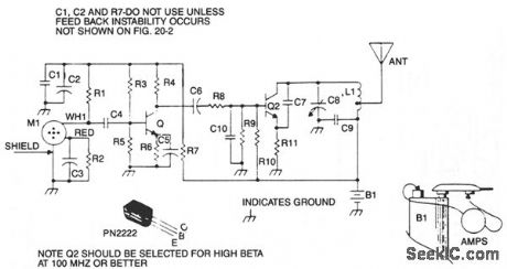
This is a sensitive, mini-powered FM transmitter consisting of an rf oscillator section interfaced with a high-sensitivity wide passband audio amplifier and capacitance microphone with built-in FET that modulates the base of the rf oscillator transistor. The setting of C8 determines the desired operating frequency-in the standard FM broadcast band, tuned to favor the high end up to 110 MHz. Capacitor C7 supplies the necessary feedback voltage developed across R11 in the emitter circuit of Q2, sustaining an oscillating condition. Resistors R9 and R10 provide the necessary bias of the base-emitter junction for proper operation, and capacitor C10 bypasses any rf to ground fed through to the base circuit. C9 provides an rf return path for the tank circuit of L1 and C8, while blocking the dc supply voltage fed to the collector of Q2. The speech voltage developed across R1 by M1 is capacitively coupled by C4 to the base of Q1. A signal voltage developed across R4 is capacity-coupled through C6 to the base of Q2 through R8. R7 and R8, along with C1 and C2, decouple the oscillator and audio circuits. (View)
View full Circuit Diagram | Comments | Reading(1115)
TWIN_OSCILLATOR_METAL_DETECTOR
Published:2009/7/8 21:21:00 Author:May

Metal object near search coil changes frequency of oscillator A1 which is initially tuned to 160 kHz,thereby changing frequency of 1-kHz output derived by mixing with 161-kHz output of A2. Sensitivity, determined largely by dimensions of search coil, is sufficient to detect coins about 1 foot away.-M. E. Anglin, C-MOS Twin Oscillator Forms Micropower Metal Detector, Electronics, Dec. 22, 1977, p 78. (View)
View full Circuit Diagram | Comments | Reading(1132)
0_35_MHz_WITH_GAIN_OF_10
Published:2009/7/8 21:14:00 Author:May


Wkleband amplifier handles inputs up to 100 mV P-P and drives 1-kilohm load, to meet requirements of oscilloscope preamps, instrumentation and pulsesignal amplifiers, and video signal processots. High-frequency gain is provided by 40673 dual-gate MOSFET. Low-frequency gain with DC stabilization is provided by CA3130 CMOS opamp. Transistors Q1-Q5 are part of CA3086 transistor-array IC. Values of R3 and R4 in feedback path establish amplifier gain. R6 sets operating point of N1 for 10-mA drain current. Base resistor ofQ3 is 1 kilohm.-H. A. Wittlinger, CMOS Op Amp, MOSFET Implement Wideband Amplifier, EDN Magazine, June 20, 1977, p 114. (View)
View full Circuit Diagram | Comments | Reading(1525)
TV_TRANSMITTER_1
Published:2009/7/8 20:58:00 Author:May

The video-link transmitter accepts color and B/W video, and audio inputs from VCRs, camcorders, small TV cameras, and microphones. The unit runs on a nominal 12 Vdc and draws 100 mA in the lowpower version, or 500 mA in the 2-W version. The kit is available from North Country Radio, P.O. Box 53, Wykagyl Station, NY 10804. (View)
View full Circuit Diagram | Comments | Reading(3240)
Hisense 628 phone cable circuit diagram
Published:2011/8/2 22:45:00 Author:Ecco | Keyword: Hisense, phone cable

View full Circuit Diagram | Comments | Reading(671)
Haier To WenXing 1000 mobile cable schematic diagram
Published:2011/8/3 2:25:00 Author:Ecco | Keyword: Haier , To WenXing 1000, mobile cable

View full Circuit Diagram | Comments | Reading(640)
HIGH_GAIN_WITH_WIDE_BANDWIDTH
Published:2009/7/8 20:50:00 Author:May


Micro Networks MN2200 instrumentation amplifier is used with strain gage to create digital-readout torque wrench.Strain gages having nominal impedance of 120 ohms are bonded to torque-sensing member at 450 to longitudinal axis, so gages in opposite bridge arms are under simultaneous tension or compression for given direction of torque.Bridge power is taken from 5-V digital panel meter supply. Instrumentation amplifier will work with any voltage from ±5 to ±15 V. Variable gain-adjust resistor G (l0-turn 50K pot) is set so DPM reads 200 ft-lb of torque at full scale in increments of 0.1 ft-lb.-R. Dulls, Instrumentation Amplifiers-They're Great Problem Solvers When Correctly Applied, EDN Magazine, Sept. 5, 1977, p 133-135. (View)
View full Circuit Diagram | Comments | Reading(534)
PORTABLE_FISH_FINDER
Published:2009/7/23 22:59:00 Author:Jessie


Measures depth up to 120 feet and provides lower-intensity echoes from schools of fish. Indicator is neon lamp at end of rotating arm driven by constant-speed motor. Magnet triggers 200-kc ultrasonic transmitter and makes neon lamp glow of zero on circular scale. Lamp glows again for each echo pulse from fish and for bottom echo.-H. C. Single, Portable Depth Finder for Small Boots, Electronics, 33:6, p 50-51. (View)
View full Circuit Diagram | Comments | Reading(3024)
MOSFET_DIFFERENTIAL_AMPLIFIER
Published:2009/7/8 20:43:00 Author:May
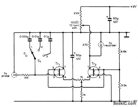
Developed to monhor chemical process of titration, by recording probe output voltages between 100 and 400 mV when intemal impedance of probe is in gigohm range. Either40673 or3N187 dualgate MOSFETs connected as differential arnpliiier are suitable for meeting high input re sistance requirement. Transistor level drifts because of temperature are in opposition and tend to cancel each other. Overall power gain of amplifier is about 70 dB. Circuit is suitable for other electrometer applications as well.-D. R. Bowman, Automatic Titration Potentiometer, Wireless World, Aug. 1971, p 400-401. (View)
View full Circuit Diagram | Comments | Reading(1082)
The ABS system circuit diagram for BMW cars
Published:2011/8/3 2:26:00 Author:Ecco | Keyword: ABS system, BMW cars
View full Circuit Diagram | Comments | Reading(547)
DIGITAL_THERMOMETER_
Published:2009/7/8 5:49:00 Author:May
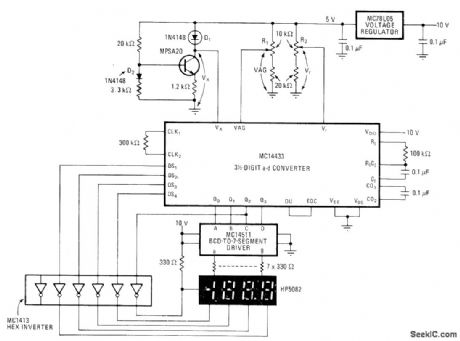
Diode D2 serves assensor for driving A/D converter directly,eliminating temperature-drift er o rs normally asso-ciated with amplifiers. Can be calibrated over temperature range of -199°to 199° in either Fahrenheit or Celsius scales. Aceuracy is about 1°-H Wurzburg and M Hadley,Digital Thor-mometer Circumvents Drift,Electronics.Jan 5,1978,p 176-177
(View)
View full Circuit Diagram | Comments | Reading(1555)
BMW 3/5/7/8 series of SRS system circuit diagram
Published:2011/8/3 1:16:00 Author:Ecco | Keyword: BMW , 3/5/7/8 series , SRS system
View full Circuit Diagram | Comments | Reading(495)
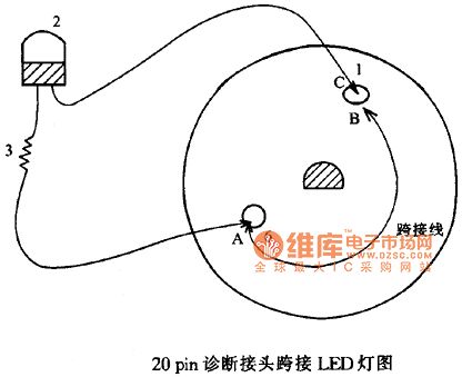
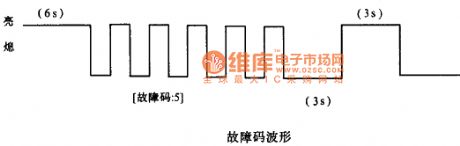
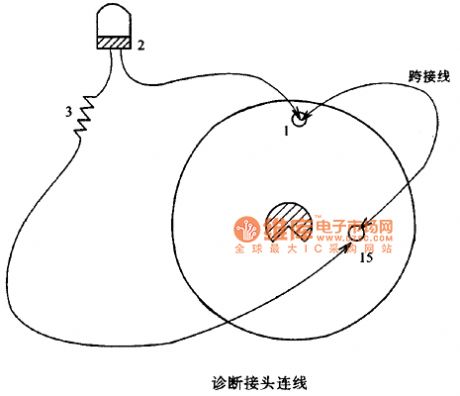
BMW SRS light flash reading fault code circuit diagram on the instrument
Published:2011/8/3 1:15:00 Author:Ecco | Keyword: BMW , SRS light flash , reading fault code , instrument
View full Circuit Diagram | Comments | Reading(461)
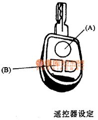
The button A circuit diagram on BMW pressing key
Published:2011/8/2 22:21:00 Author:Ecco | Keyword: button A , BMW pressing key
View full Circuit Diagram | Comments | Reading(511)
BMW 6 Series of 55-pin computer SRS system circuit diagram
Published:2011/8/2 22:50:00 Author:Ecco | Keyword: BMW , 6 Series , 55-pin computer , SRS system
View full Circuit Diagram | Comments | Reading(490)
Auto Parallel Charger Circuit
Published:2011/8/1 6:14:00 Author:Zoey | Keyword: Auto Parallel, Charger Circuit

T2, T4, T6, T8 and the relevant accessories constitute a constant circuit, the charge current is 50mA and 120mA.As soon as swtich K is closed, the charge current will turn to be 50mA; and if K is disconnected, the charge current will turn to be 120mA. Triode T1, T3, T5 and T7 and the rellevant accessories constitute a detection citcuit that is in a charge state. Potentiometer W is used to set to charge voltage. When it is fully charged, the battery will turn into a trickle maintain state. Trickle is set about 9mA by the resistances R4, R7,R10 and R13. (View)
View full Circuit Diagram | Comments | Reading(1071)
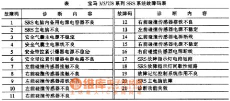
BMW 3/5/7/8 series of SRS system fault code table circuit diagram
Published:2011/8/2 22:47:00 Author:Ecco | Keyword: BMW , 3/5/7/8 series , SRS system , fault code table
View full Circuit Diagram | Comments | Reading(575)
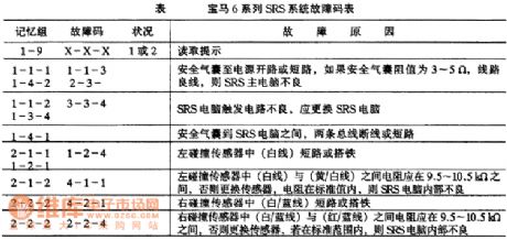
BMW 6 Series of SRS system fault code table circuit diagram
Published:2011/8/2 22:30:00 Author:Ecco | Keyword: BMW 6 Series , SRS system, fault code table
View full Circuit Diagram | Comments | Reading(495)
BMW 3/5/7/8 series of SRS system circuit diagram 1
Published:2011/8/2 22:37:00 Author:Ecco | Keyword: BMW , 3 series, 5 series, 7 series, 8 series, SRS system

View full Circuit Diagram | Comments | Reading(566)
BMW 3/5/7/8 series of SRS system circuit diagram 2
Published:2011/8/2 22:38:00 Author:Ecco | Keyword: BMW , 3 series, 5 series, 7 series, 8 series, SRS system

View full Circuit Diagram | Comments | Reading(460)
| Pages:937/2234 At 20921922923924925926927928929930931932933934935936937938939940Under 20 |
Circuit Categories
power supply circuit
Amplifier Circuit
Basic Circuit
LED and Light Circuit
Sensor Circuit
Signal Processing
Electrical Equipment Circuit
Control Circuit
Remote Control Circuit
A/D-D/A Converter Circuit
Audio Circuit
Measuring and Test Circuit
Communication Circuit
Computer-Related Circuit
555 Circuit
Automotive Circuit
Repairing Circuit