Communication Circuit
FM_VOICE_TRANSMITTER
Published:2009/7/8 21:27:00 Author:May | From:SeekIC

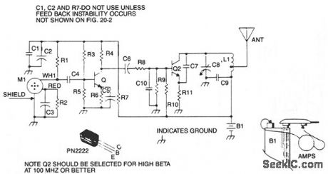
This is a sensitive, mini-powered FM transmitter consisting of an rf oscillator section interfaced with a high-sensitivity wide passband audio amplifier and capacitance microphone with built-in FET that modulates the base of the rf oscillator transistor. The setting of C8 determines the desired operating frequency-in the standard FM broadcast band, tuned to favor the high end up to 110 MHz. Capacitor C7 supplies the necessary feedback voltage developed across R11 in the emitter circuit of Q2, sustaining an oscillating condition. Resistors R9 and R10 provide the necessary bias of the base-emitter junction for proper operation, and capacitor C10 bypasses any rf to ground fed through to the base circuit. C9 provides an rf return path for the tank circuit of L1 and C8, while blocking the dc supply voltage fed to the collector of Q2. The speech voltage developed across R1 by M1 is capacitively coupled by C4 to the base of Q1. A signal voltage developed across R4 is capacity-coupled through C6 to the base of Q2 through R8. R7 and R8, along with C1 and C2, decouple the oscillator and audio circuits.
Reprinted Url Of This Article:
http://www.seekic.com/circuit_diagram/Communication_Circuit/FM_VOICE_TRANSMITTER.html
Print this Page | Comments | Reading(3)

Article Categories
power supply circuit
Amplifier Circuit
Basic Circuit
LED and Light Circuit
Sensor Circuit
Signal Processing
Electrical Equipment Circuit
Control Circuit
Remote Control Circuit
A/D-D/A Converter Circuit
Audio Circuit
Measuring and Test Circuit
Communication Circuit
Computer-Related Circuit
555 Circuit
Automotive Circuit
Repairing Circuit
Code: