
Circuit Diagram
Index 927
HARTLEY_JFET_OSCILLATOR
Published:2009/7/21 2:19:00 Author:Jessie

This simple Hartley JFET oscillator has a built-in zener-diode regulator to condition the power-supply voltage down to 9.1 V. L1 depends on the desired frequency. Typical values are C1=5 to 50pF variable, C2=100 pF plus a 3-to 30-pF trimmer, and L1=14μH (for 3.5 MHz). L1 should be mechanically rigid, should have an air core (do not use ferrite cores because of drift effects), and should have Q ≥ 200 for best stability. The tap will be typically 10 to 25 percent of the total turns. (View)
View full Circuit Diagram | Comments | Reading(1325)
10_GHz_2_STAGE_PREAMP
Published:2009/7/8 23:11:00 Author:May
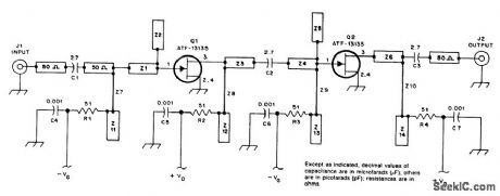
This preamp uses two ATF 13135 stages for typically 17-dB gain and less than 2 dB NF. (View)
View full Circuit Diagram | Comments | Reading(502)
NE602_OSCILLATOR_CIRCUIT
Published:2009/7/21 2:28:00 Author:Jessie

If the LO signal of the NE602 is sent directly to the output pins, the device can be used as a low-cost, high-frequency oscillator. (View)
View full Circuit Diagram | Comments | Reading(1166)
ELECTRONIC_TREMOLO
Published:2009/7/8 23:10:00 Author:May
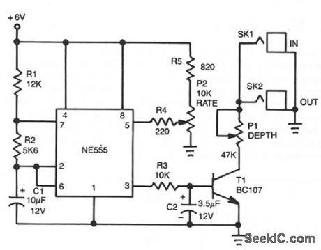
The tremolo effect is generated by a repeating volume change at a rate usually between 1 and 15 Hz. The timer produces a low frequency square wave that is smoothed by a simple rc integrator. This varying signal modulates the signal input from the instrument. Transistor T1 is used as a voltage controlled resistor. The output of the circuit is connected in parallel to the output of the instrument. Potentiometer P1 provides depth control by adjusting the amplitude of the modulating waveform applied to the instrument. The rate control frequency is set by potentiometer P2. (View)
View full Circuit Diagram | Comments | Reading(2316)
Three-phase motor phase failure protection circuit diagram
Published:2011/8/2 2:23:00 Author:Rebekka | Keyword: Three-phase motor, phase failure protection
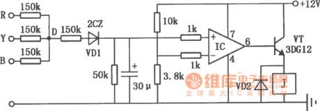
The circuit is composed of general purpose integrated operational amplifiers. The circuit is shown as above. It can be used in a variety of three-phase motor phase protections. IC uses a typical general-purpose integrated operational amplifiers, such as 5G24, BG305, FC4, F006, XFC77 or other foreign products μA741 etc. The relay J can use DC l2V operating voltage, the DC resistance is 200Ω DC relay. (View)
View full Circuit Diagram | Comments | Reading(3545)
Latch_circuit_using_an_LM3909_chip
Published:2009/7/21 2:39:00 Author:Jessie

Latch circuit using an LM3909 chip. Circuitry inside dashed lines is the LM3909, The circuit switches to and holds its condition whenever the switch changes sides (courtesy National Semiconductor Corporation). (View)
View full Circuit Diagram | Comments | Reading(637)
Line current restrictor circuit diagram
Published:2011/8/2 2:24:00 Author:Rebekka | Keyword: Line current restrictor

The figure shows the current of the line current restrictor limit circuit. Once the value of the current exceeds the limit value, the controller relay will cut off the power supply immediately. The current limit value is continuously adjustable from l00mA to 10A. The components of the circuit is shown as above. The whole circuit includs the line current sample and voltage comparator, RS flip-flop and control relay. It is composed of an operational amplifier MA741 and a four - two input NAND gate CD4011. (View)
View full Circuit Diagram | Comments | Reading(854)
Discrete_level_shifting_circuit
Published:2009/7/21 2:41:00 Author:Jessie
Discrete level-shifting circuit (courtesy Motorola Semiconductor Products Inc.). (View)
View full Circuit Diagram | Comments | Reading(904)
Pulse_position_modulator_using_an_ECG955M_timer
Published:2009/7/21 2:43:00 Author:Jessie

Pulse position modulator using an ECG955M timer/oscillator chip. The timer is connected as an astable multivibrator. With a modulating signal applied to pin 5 the pulse positon will vary with the modulating signal (courtesy GTE Sylvania Incorporated). (View)
View full Circuit Diagram | Comments | Reading(612)
Cosine_function_from_the_4301_multifunction_chip
Published:2009/7/21 2:47:00 Author:Jessie
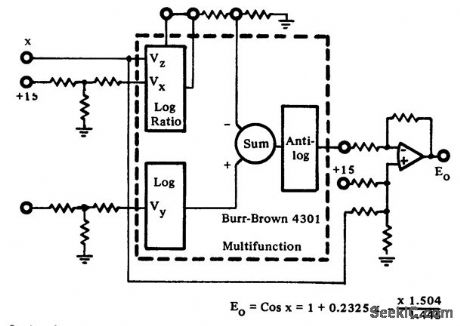

Cosine function from the 4301 multifunction chip (courtesy Burr-Brown Research Corporation). (View)
View full Circuit Diagram | Comments | Reading(581)
Uninterrupted power supply circuit composed of MIC5158
Published:2011/8/2 2:25:00 Author:Rebekka | Keyword: Uninterruptible power supply
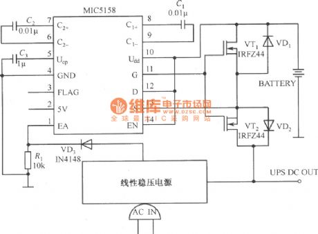
Uninterrupted power supply circuit composed of MIC5158 is shown as above. The circuit uses MIC5158 to control the uninterrupted power supply which formed by the source electrode of two N-channel tubes. The source electrodes of the 2 N-channel tubes are connected. This can avoid the current from passing the internal diode of integrated voltage regulator. This kind of low dropout regulator can control the battery switch rapidly. The most critical function of the exchange network line monitor is to the output voltage is lower than the designed limiting voltage when the batterr works online. (View)
View full Circuit Diagram | Comments | Reading(716)
Driving Circuit Transformer Primary And Secondary Circuit
Published:2011/8/3 10:18:00 Author:Robert | Keyword: Driving, Transformer, Primary, Scondary

The picture shows the IGBT switch tube's driving circuit transformer primary and secondary principle circuit. The R235-R238 are grid electrode series resistance. It is important for IGBT grid electrode driving by selecting adequate grid electrode series resistors.Its openning and closing are achieved by the grid electrode circuit's charging and discharging. The grid electrode resistor with low value would make the grid electrode capacitot's charging and discharging be fast. So it would reduce the switching time and switching power consumption. When it has short circuits or it is during the closing time of fly-wheel diode which has bridge connection to the crossing IGBT, the added du/dt on the IGBT and its collector polar's a grid electrode capacitor could cause the case that there is current through the grid electrode circuit. If this current is large enough, this would generate voltage between grid electrode resistors and make the IGBT be wrong connected. (View)
View full Circuit Diagram | Comments | Reading(736)
STRIP_LINE_OSCILLATOR
Published:2009/7/21 2:48:00 Author:Jessie

The figure shows a prototype strip tine oscillator that is capable of providing an operating range of 3.5:1 before oscillation ceases Length A∶40 mm,width B∶2 mm,width C:1 mm To change the frequency range,alter the length A and the length of the output coupling wire Typical frequencies with C=0 pF are about 145 MHz;with 27 pF, about 80 MHz; with 56 pF, about 60 MHz;and with 150 pF, about 36 MHz (plate-ceramic capacitors). With 1/16-inch double-sided PC board, note that the bottom ground plane covers the whole of the board. The output is about 0 dBm. The U310 FET is pushed through from the bottom side of the PC board until it touches the ground plane and is soldered directly to the ground plane. (View)
View full Circuit Diagram | Comments | Reading(693)
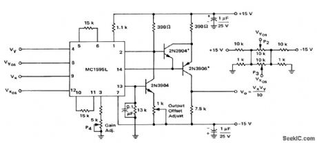
True_PMS_circuit_using_one_AD531_multiplier_divider_and_two_AD741_op_amps
Published:2009/7/21 2:49:00 Author:Jessie

True PMS circuit using one AD531 multiplier/divider and two AD741 op amps. The AD531 is combined with a simple filter to obtain the true PMS value of an AC input signal. By scaling VOUT=10 volts DC for a ±10-volt DC input this circuit can give direct RMS readings for 100 hertz to 100 kilohertz sine waves from 0.2 volt to 7.0 volts peak (courtesy Analog Devices, Inc.). (View)
View full Circuit Diagram | Comments | Reading(721)
SIGNAL_STRENGTH_METER
Published:2009/7/8 23:09:00 Author:May

This fteld-strength meter is useful for antenna testing. It covers 6 to 60 MHz and uses a rugged 0-to-1 mA meter. A 9-V battery supplies power. The unit can be mounted in a small plastic or metal case. (View)
View full Circuit Diagram | Comments | Reading(899)
4_to_20_ma_current_transmitter
Published:2009/7/21 2:50:00 Author:Jessie
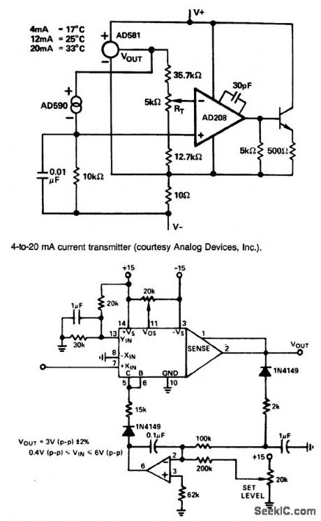

4-to-20 ma current transmitter (courtesy Analog Devices, Inc). (View)
View full Circuit Diagram | Comments | Reading(842)
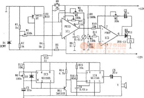
Negative pressure switch regulated power supply circuit diagram
Published:2011/8/2 2:26:00 Author:Rebekka | Keyword: Negative pressure switch, Vacuum switch regulated power supply
View full Circuit Diagram | Comments | Reading(856)
Automatic reset over-voltage protection circuit diagram
Published:2011/8/3 2:40:00 Author:Rebekka | Keyword: Automatic reset, Over-voltage protection
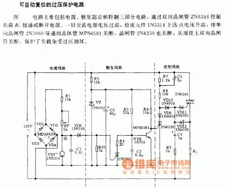
The circuit includes 3 circuit parts:power supply, trigger start and control. The power supply switch of the load R1 is controlled by bidirectional thyristor ZN6346. When the AC voltage is over high, the A point voltage of steady flow component 1N5314 will rise and the unidirectional thyristor will be conducted and the transistor will be closed. The main bidirectional thyristor will be closed at the same time, the load will be protected from damaging. (View)
View full Circuit Diagram | Comments | Reading(1163)
Storehouse temperature measurement alarm circuit diagram
Published:2011/8/3 2:41:00 Author:Rebekka | Keyword: Storehouse temperature measurement alarm
View full Circuit Diagram | Comments | Reading(584)
±5 to ±l8V adjustable tracking regulated power supply circuit diagram
Published:2011/5/10 2:30:00 Author:Rebekka | Keyword: regulated power supply

View full Circuit Diagram | Comments | Reading(662)
| Pages:927/2234 At 20921922923924925926927928929930931932933934935936937938939940Under 20 |
Circuit Categories
power supply circuit
Amplifier Circuit
Basic Circuit
LED and Light Circuit
Sensor Circuit
Signal Processing
Electrical Equipment Circuit
Control Circuit
Remote Control Circuit
A/D-D/A Converter Circuit
Audio Circuit
Measuring and Test Circuit
Communication Circuit
Computer-Related Circuit
555 Circuit
Automotive Circuit
Repairing Circuit