
Circuit Diagram
Index 931
Digitally_programmed_set_point_comparator
Published:2009/7/21 3:04:00 Author:Jessie

Digitally programmed set point comparator (courtesy Analog Devices, Inc.). (View)
View full Circuit Diagram | Comments | Reading(599)
10_GHz_SINGLE_STAGE_PREAMP
Published:2009/7/8 22:45:00 Author:May

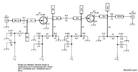
Using a single Avantek ATF 13135 GASFET, this preamplifier has 8-dB gain (typically)and1.7-dB nolse figure.The PC boardis 0.031'',doublesided,with E=2.2. (View)
View full Circuit Diagram | Comments | Reading(738)
AD_BOARD
Published:2009/7/8 22:44:00 Author:May
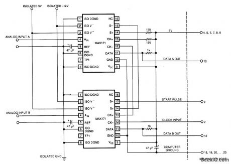
An IBM PC can operate the two 12-bit A/D converters in Fig. 1 via its printer port. The converters' serial outputs use only two of the printer port's eight data lines (DATA A OUT, DATA B OUT). Because the IBM PC's printer port supplies no power, interface software running on the PC programs the six unused data lines high. Busing these data lines provides power for the digital portion of the A/D con-verters. (The converters have internal optoisolators. Consequently, you must provide isolated supplies for their analog sides.)
Although the converters can execute 12-bit conversions in 6 μs, the slow software-driven approach used in this Design Idea stretches conversion periods out to about 100 μs (depending on your PC's clock speed).
The circuit takes advantage of the converters' optoisolator inputs to put their clock and start inputs in series. Therefore, the converters operate synchronously.
The accompanying software starts the conversions, issues clock pulses, reads the data bits as they become available, and stores them in memory. The listing is too long to reproduce here; you can obtain it from the EDN BBS (617-558-4241, 2400, 8, N, 1). (View)
View full Circuit Diagram | Comments | Reading(667)
ADJUSTABLE_DUTY_CYCLE_SQUARE_WAVE_OSCILLATOR
Published:2009/7/21 3:04:00 Author:Jessie
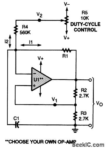
Use R5 to adjust this variable-duty-cycle square-wave generator. That potentiometer controls I2 to vary the timing. (View)
View full Circuit Diagram | Comments | Reading(1496)
AMBIENT_LIGHT_GNORING_OPTICAL_SENSOR
Published:2009/7/8 22:44:00 Author:May

A resonance-tuned narrow-band amplifier reduces this optical object detector's sensitivity to stray light. C1 and L1 in IC2A's feedback loop cause the op amp to pass only those frequencies at or near the LED's 5-kHz modulation rate. IC2B's output increases when the received signal is sufficient to drop the negative voltage across C2 below the reference set by R2.
(View)
View full Circuit Diagram | Comments | Reading(1462)
FAST_RESPONSESETTLINGLOW_PASS_FILTER
Published:2009/7/8 22:44:00 Author:May

This circuit uses a Wien Bridge and variable negative feedback. R7 controls the gain and R8A and R8B controls the tuned frequency. (View)
View full Circuit Diagram | Comments | Reading(667)
LJC2200 (air conditioner, electric fan, radio, television and toy) infrared, ultrasonic and radio remote control receiving circuit
Published:2011/7/27 22:03:00 Author:TaoXi | Keyword: air conditioner, electric fan, radio, television , toy, infrared, ultrasonic, radio, remote control, receiving circuit

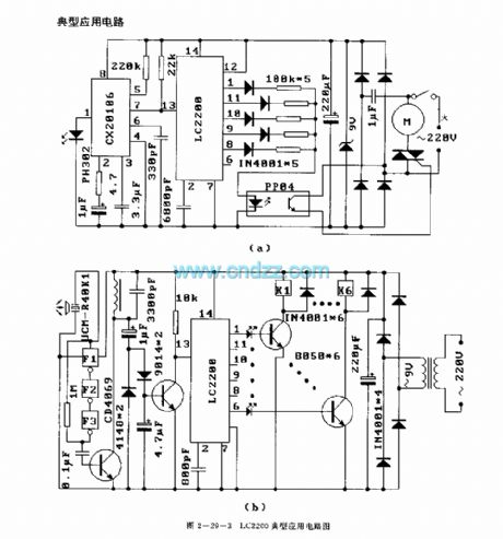

The LC2200 is designed as the infrared, ultrasonic and radio remote control receiving circuit that can be used in the air conditioner, electric fan, radio, television and toy applications. The internal circuit is composed of the input buffer circuit, the fault detection circuit, the timing circuit, the decoder, the boot-reset circuit, the mode control circuit, the latch and output driver circuit.
Features
Low power consumption.Good anti-interference performance.Little external components.Easy to use.The matching model is LC2190.
(View)
View full Circuit Diagram | Comments | Reading(1033)
INDICATOR_LAMP_DRIVER
Published:2009/7/8 22:43:00 Author:May

A simple solid-state relay circuit drives the 10-Vac telephone indicator lamps from logic circuitry, while maintaining complete isolation between the 10-V line and the logic circuit. (View)
View full Circuit Diagram | Comments | Reading(688)
LB1475 (video tape recorder) two-wire wired remote control circuit
Published:2011/7/27 22:15:00 Author:TaoXi | Keyword: video tape recorder, two-wire, wired, remote control circuit


FeaturesYou can complete 13 kinds of remote control functions by using only two control lines between the controller and the remote control equipment.
It has the monostable multivibrator, the oscillation frequency is controlled by the external components, and this monostable multivibrator can be used to inhibit the disturbance which is produced by the switch conversion; when you do not want to use the monostable multivibrator, you can connect the pin-16 with the ground.
It can drive the light-emitting diode directly.
20-pin dual-row DIP package.
(View)
View full Circuit Diagram | Comments | Reading(1995)
NORMALLY_OPEN_AND_NORMALLY_CLOSED_DC_SOLID_STATE_RELAYS
Published:2009/7/8 22:42:00 Author:May
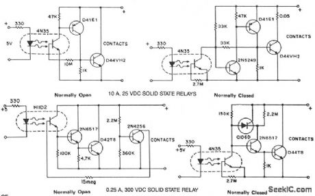
The phototransistor and photodarlington couplers act as dc relays in saturated switching at currents up to 5 mA and 50 mA, respectively. When higher currents or higher voltage capabilities are required, additional devices are required to buffer or amplify the photocoupler output. The addition of hysteresis to provide fast switching and stable pick-up and drop-out points can be easily implemented simultaneously.These circuits provide several approaches to implement the dc relay function and serve as practical, costeffective examples. (View)
View full Circuit Diagram | Comments | Reading(1595)
LM909 (electronic toys) radio remote control receivier decoding circuit
Published:2011/7/28 0:53:00 Author:TaoXi | Keyword: electronic toys, radio, remote control, receivier, decoding circuit
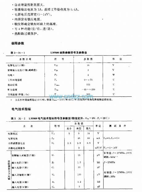

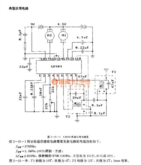
The LM909 is designed as the radio remote control receivier decoding circuit that can be used in the electronic toys application. The circuit is composed of the radio frequency amplifier, the automatic gain control (AGC) circuit, the wave detector, the phase locked loop, the level detection circuit and the push-pull output circuit.
Features
The decoding frequency is 40MHz.The RF sensitivity is high.It has the audio PLL demodulator.The automatic gain control range is wide.The surge output current is 1A, the continuous operating current is 0.6A.The power supply voltage range is wide (5-14V).It has the voltage-stabilized power supply.
(View)
View full Circuit Diagram | Comments | Reading(1886)
Square_rooter_circuit_using_an_AD532_multiplier_divider_chip
Published:2009/7/21 4:35:00 Author:Jessie
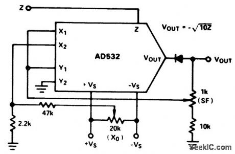
Square rooter circuit using an AD532 multiplier/divider chip. The AD532 is available as a 10-pin TO-100 or as a 14-pin DIP (courtesy Analog Devices,Inc.). (View)
View full Circuit Diagram | Comments | Reading(563)
57_GHz_MICROWAVE_AMPLIFIER
Published:2009/7/8 22:41:00 Author:May
This preamplifier has a typical gain of 17 dB and NF=1.2 dB or better. If a 0.031 PC board (with a dielectric constant of 2.2) is used, the reverse side is unetched. (View)
View full Circuit Diagram | Comments | Reading(892)
A_ONE_TRANSISTOR_FM_TRANSMITTER
Published:2009/7/8 22:40:00 Author:May
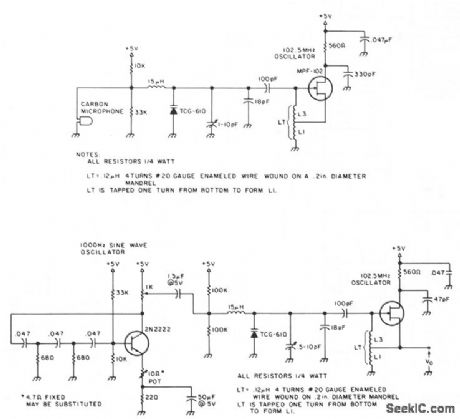
The 2N2222 circuitry is a three-element, phase-shift oscillator circuit, designed to yield a 1,000-Hz sine wave. The 1,000-Hz sine wave is then applied to the TCG-610 varactor diode, 6 pF at 4 V, which changes the tank capacitance, thus varying the rf oscillator frequency at a 1,000-Hz rate. The 1,000-Ω potentiometer in the collector circuit can be adjusted to enable the desired frequency modulation level.The Hartley rf oscillator, designed around a readily available MPF-102 JFET, has an output that should be relatively stable if it is enclosed in a metal box, thus minimizing changes in tank capacitance. The completed transmitter has a range of 30 feet when not enclosed-without an antenna. (View)
View full Circuit Diagram | Comments | Reading(2917)
LM1872 (electronic toys and model cars) radio, infrared ray remote control receiving decoder circuit
Published:2011/7/28 1:08:00 Author:TaoXi | Keyword: electronic toys, model cars, radio, infrared ray, remote control, receiving, decoder circuit
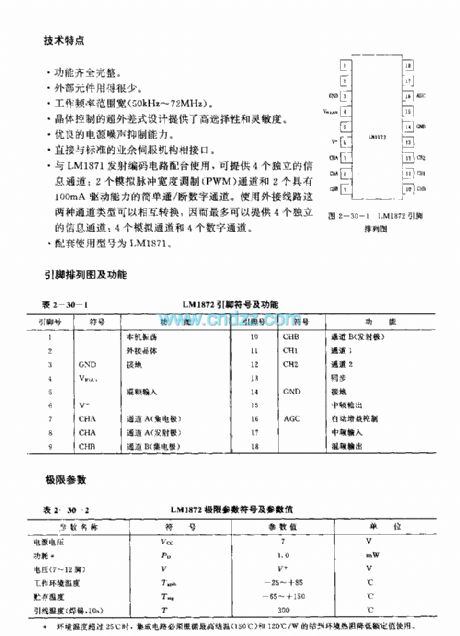
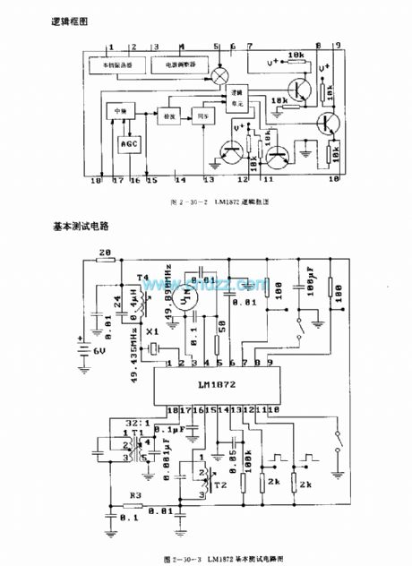

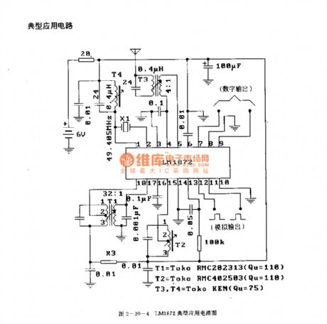
The LM1872 is designed as the radio or infrared ray remote control receiving decoder circuit that can be used in the electronic toys and model cars. The internal circuit is composed of the logic unit circuit, the local oscillator, the voltage regulator, the intermediate frequency circuit, the AGC circuit, the wave detector and the synchronous circuit.
Features
The function is complete.The external components is few.The operating frequency is wide (50kHz-72MHz).The specialized superheterodyne type design supplies the high selectivity and sensitivity.It has good power supply noise rejection capability.It connects with the standard spare servo mechanism directly.The matching model is LM1871.
(View)
View full Circuit Diagram | Comments | Reading(3172)
NORMALLY_CLOSED_HALF_WAVE_zvs_CONTACT_CIRCUIT
Published:2009/7/8 22:39:00 Author:May

A normally closed contact circuit that provides zero-voltage switching is designed around the 4N39 SCR optocoupler. The circuit illustrates the method of modifying the normally open contact circuit by using the photo SCR to hold off the trigger SCR. (View)
View full Circuit Diagram | Comments | Reading(1297)
WIDEBAND_ACTIVE_ROD_ANTENNA
Published:2009/7/8 22:36:00 Author:May

A J309 Siliconix FET feeds a 2N5109 in a wideband RF amplifier configuration. A relay is used to bypass the amplifier in the transmit mode (if desired). A 2-m 5/8-wave whip is used as the active antenna element. The amplifier is fed dc via the coax cable, which makes the use of only a single coax lead for both signal and power. U1 is a surge arrester for electrostatic discharge protection. (View)
View full Circuit Diagram | Comments | Reading(2713)
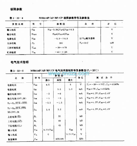
M50116P/AP/BP/CP (video recorder, TV and audio equipment) 60-function infrared remote control receiving circuit
Published:2011/8/1 4:57:00 Author:TaoXi | Keyword: video recorder, TV, audio equipment, 60-function, infrared, remote control, receiving circuit

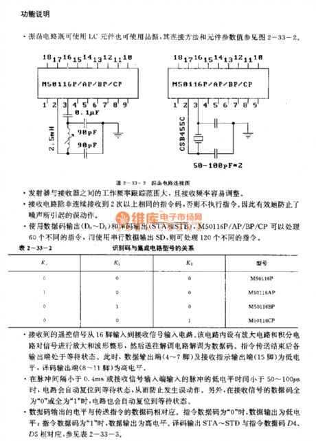
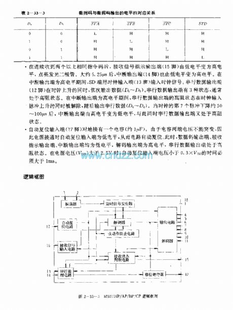
The M50116P/AP/BP/CP is designed as the 30-function infrared remote control receiving circuit that can be used in the video recorder, TV and audio equipment applications. The internal circuit is composed of the receiving signal input circuit, the demodulator, the receiving state discriminant circuit, the oscillator, the timing signal generator, the malfunction prevention circuit, the serial processing circuit, the shifting register and the automatic reset circuit. The differences between the M50116P, M50116AP, M50116BP, M50116CP are the identification numbers.
Features
CMOS large scale integrated circuit, the power consumption is low.When it uses the single power operating mode, the power voltage is 4.5-8V.The high sensitivity, fast receiving speed.18-pin dual-row DIP plastic package.The matching models are M50116P, M50116AP, M50116BP, M50116CP and M50115P, M50115AP, M50115BP, M50115CP.
(View)
View full Circuit Diagram | Comments | Reading(1308)
M50117F/AP/BP/CP (VCR, TV and audio equipment) 120-function infrared remote control receiver circuit
Published:2011/8/1 5:01:00 Author:TaoXi | Keyword: VCR, TV, audio equipment, 120-function, infrared, remote control, receiver circuit


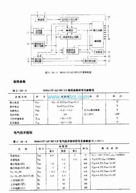
The M50117F/AP/BP/CP is designed as the 120-function infrared remote control receiving circuit that can be used in the video recorder, TV and audio equipment applications. The internal circuit is composed of the receiving signal input circuit, the demodulator, the receiving state discriminant circuit, the oscillator, the timing signal generator, the malfunction prevention circuit, the serial processing circuit, the shifting register and the automatic reset circuit. The differences between the M50117P, M50117AP, M50117BP, M50117CP are the identification numbers.
Features
CMOS large scale integrated circuit, the power consumption is low.When it uses the single power operating mode, the power voltage is 4.5-8V.The high sensitivity, fast receiving speed.18-pin dual-row DIP plastic package.The matching models are M50110P, M50110AP, M50110BP, M50110CP and M50115P, M50115AP, M50115BP, M50115CP.
(View)
View full Circuit Diagram | Comments | Reading(1204)
M50111P/AP/BP/CF (video recorder, television and audio equipment) 30-function infrared remote control receiver circuit
Published:2011/8/1 5:04:00 Author:TaoXi | Keyword: video recorder, television, audio equipment, 30-function, infrared, remote control, receiver circuit


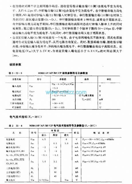

The M50111P/AP/BP/CF is designed as the 30-function infrared remote control receiving circuit that can be used in the video recorder, TV and audio equipment applications. The internal circuit is composed of the receiving signal input circuit, the demodulator, the receiving state discriminant circuit, the oscillator, the timing signal generator, the malfunction prevention circuit, the serial processing circuit, the shifting register and the automatic reset circuit. The differences between the M50117P, M50117AP, M50117BP, M50117CP are the identification numbers.
Features
CMOS large scale integrated circuit, the power consumption is low.When it uses the single power operating mode, the power voltage is 2.2-8V.The high sensitivity, fast receiving speed.16-pin dual-row DIP plastic package.The matching models are M50110P, M50110AP, M50110BP, M50110CP.
(View)
View full Circuit Diagram | Comments | Reading(1561)
| Pages:931/2234 At 20921922923924925926927928929930931932933934935936937938939940Under 20 |
Circuit Categories
power supply circuit
Amplifier Circuit
Basic Circuit
LED and Light Circuit
Sensor Circuit
Signal Processing
Electrical Equipment Circuit
Control Circuit
Remote Control Circuit
A/D-D/A Converter Circuit
Audio Circuit
Measuring and Test Circuit
Communication Circuit
Computer-Related Circuit
555 Circuit
Automotive Circuit
Repairing Circuit