
Circuit Diagram
Index 941
NERVE_ACTION_POTENTIAL_TRANSMITTER
Published:2009/7/20 21:08:00 Author:Jessie

Used in telemetering bioelectric potentials from baroreceptors of blood pressure control system in active awake animals for several days after surgical implantation of electrodes in aorta and carotid arteries. System provides lat frequency response from 1 to 1,200 cps with input impedance of 2.5 meg and input sensitivity of 5 to 500 my. Trans-mining range is 25 feet.-P. Kezdi and W. S.Naylor, Telemetry System to Transmit Baroreceptor Nerve Action Potentials, The American Journal of Medical Electron; 4:4,p 153-155. (View)
View full Circuit Diagram | Comments | Reading(738)
Duty_cycle_and_frequency_control_circuitry_for_a_switching_mode_regulator
Published:2009/7/20 21:08:00 Author:Jessie

Duty cycle and frequency control circuitry for a switching mode regulator.Q1 sets the basic operating frequency of the regulator at 5 kHz, while Q4 controls the duty cycle (courtesy Motorola Semiconductor Products Inc.). (View)
View full Circuit Diagram | Comments | Reading(640)
PULSE_CROSS_DISPLAY_GENERATOR
Published:2009/7/20 21:07:00 Author:Jessie

Phantastron circuits delay horizontal and vertical sync pulses, when added to monitor or tv receiver, to provide display for checking operation of tv station sync generator.-H. E. O'Kelley, Pulse-Cross Modification of Tv Receivers, Electronics, 31:9, p 54-55. (View)
View full Circuit Diagram | Comments | Reading(729)
FOETAL_HEART_BEAT_DETECTOR
Published:2009/7/20 21:07:00 Author:Jessie

Amplified 2- to 3-cps signal from foetal heart modulates transistor oscillator operating between 800 and 1,200 cps. Frequency modulation technique overcomes poor low-frequency response of human ear and loudspeaker. A-c coupled stages have large lime constants, to give required low-frequency response.-T. I. Humphreys, Transistor Unit Detects Foetal Heart Sounds, Electronics, 31:17, p 52-54. (View)
View full Circuit Diagram | Comments | Reading(989)
Fixed_negative_voltage_regulator_using_the_μA79HG_which_can_supply_a_minimum_of_5_amperes_at_voltages_from__23_volts_to__24_volts_
Published:2009/7/20 21:06:00 Author:Jessie

Fixed negative voltage regulator using the μA79HG, which can supply a minimum of 5 amperes at voltages from -2.3 volts to -24 volts (courtesy Fairchild Semiconductor). (View)
View full Circuit Diagram | Comments | Reading(537)
Negative_floating_regulator100_volts_using_an_ECG915_or_ECG915D_IC
Published:2009/7/20 21:22:00 Author:Jessie

Negative floating regulator(100 volts) using an ECG915 or ECG915D IC.For a ±5% fixed output, H1 should be 3.57 ohms and R2 should be 97.6 ohms (courtesy GTE Sylvania Incorporated). (View)
View full Circuit Diagram | Comments | Reading(575)
TRUE_TWIN_TRIODE_CASCODE
Published:2009/7/20 21:22:00 Author:Jessie

Use of 5-mfd capacitor across regulated output reduces adverse effect of 2.2-meg plate load resistor g frequency response. Cascade circuit is Used when required gain is too high for single triode because it avoids need for second d-c supply that would be required for screen if pentode were used.-NBS, Handbook Preferred Circuits Navy Aeronautical Electronic Equipment, Vol. 1 Electron lube Circuits, 1963, p N2-2. (View)
View full Circuit Diagram | Comments | Reading(771)
100_volt_RMS_regulator_using_a_triac_and_UJT
Published:2009/7/20 21:21:00 Author:Jessie

100-volt RMS regulator using a triac and UJT. To eliminate 60-hertz modulation of the photocell it is mounted at one end of a black tube with the other end directed at the back side of the lamp reflector. The reflector glows red and since it has a relatively large mass it cannot respond to the supply frequency. This provides a form of integration (courtesy Motorola Semiconductor Products Inc.). (View)
View full Circuit Diagram | Comments | Reading(1436)
MODIFIED_TWIN_TRIODE_CASCODE
Published:2009/7/20 21:21:00 Author:Jessie

Plate resistor for lower-potention triode parallels top triode, which is plate load for true cascode. This increases gain of circuit by increasing average plate current and thereby transcon-ductance of bottom triode.-NBS, Handbook Preferred Circuits Navy Aeronautical Electronic Equipment, Vol. 1, Electron Tube Circuits, 1963, p N2-2. (View)
View full Circuit Diagram | Comments | Reading(817)
NONINVERTING_SAMPLE_AND_HOLD
Published:2009/7/20 21:21:00 Author:Jessie

Matched pair of FETs gives high input resistance for analog input signal greater than 1012 ohms, while output resistance of FET pair is under 12K. Opamp A1 acts as buffer and allows C1 to charge rapidly. Use of DG181 analog switches limits leakage current flowing into or out of C1, while SW2 provides fast resetting of capacitor voltage to zero. Similar FET pair and opamp provide output voltage proportional to sampled value.- Analog Switches and Their Applications, Siliconix, Santa Clara, CA, 1976, p 4-7-4-8. (View)
View full Circuit Diagram | Comments | Reading(628)
INVERTED_OUTPUT_SWITCHING_REGULATOR
Published:2009/7/20 21:20:00 Author:Jessie

Simple 6-kc blocking oscillator circuit serves both for sensing and duty cycle control. Arrangement is more efficient than conventional series-pass regulators. Inverted polarity is added feature. Will regulate 20-v output within 1% overload range of 50 ma to 1 amp.-H. Weber, Two Unique Switching Voltage Regulators Using Blocking Oscillators, Motorola Application Note AN-163, Aug. 1965. (View)
View full Circuit Diagram | Comments | Reading(658)
PRESET_PULSE_COUNTER
Published:2009/7/20 21:19:00 Author:Jessie

Automatically controls lesion-producing ultrasonic radiation counting up to 99,999. Mechanical counter is actuated by thyratron V5, which is keyed by on by 50-millisec counter pulser driven by leading edge of square wave input pulse.- B. J. Cosman and T.F. Hueter, Instrumentation for Ultrasonic Neurosurgery Electronics,32:20,p 53-57. (View)
View full Circuit Diagram | Comments | Reading(798)
256_8_BIT_SAMPLE_STORE
Published:2009/7/20 21:18:00 Author:Jessie

Low-cost substitute for storage oscilloscope can be used to study analog variables in speech synthesis, transient signal analysis, and destructive testing of components. Circuit is basically a tracking A/D convener whose digital output is fed into shift register holding 256 8-bit words. Separate clock for shift register is continuously adjustable from about 250 kHz down to about 4 s per cycle, with output going to 12-stage ripple counter. At 250 kHz, shift register stores input signal for t ms. Article gives details of circuit operation.-K. P. Roby, Transient Signal Analyzer Has Multiple Uses, EDN Magazine, Oct. 20,1974,p 46-48. (View)
View full Circuit Diagram | Comments | Reading(1184)
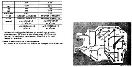
3_watt_5_watt_AF_power_amplifier_with_NPN_driver
Published:2009/7/20 21:18:00 Author:Jessie

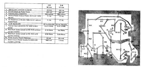
3-watt/5-watt AF power amplifier with NPN driver (courtesy Motorola Semiconductor Products Inc.). (View)
View full Circuit Diagram | Comments | Reading(1807)
20_watt_3_phase_inverter_with_12_volt_DC_input_and_115_volt_400_hertz_AC_output
Published:2009/7/20 21:17:00 Author:Jessie


20-watt 3-phase inverter with 12-volt DC input and 115-volt 400-hertz AC output (courtesy Motorola Semiconductor Products Inc.). (View)
View full Circuit Diagram | Comments | Reading(5085)
TRACK_AND_HOLD
Published:2009/7/20 21:15:00 Author:Jessie

When track input control is 0.8V or less, gate in SN75180 holds 2N4391 transistor source-drain path closed so input signal goes to output unchanged. When control voltage is increased to 2 V, gate opens path through transistor, so signal voltage stored at that instant in 0.1-μF capacitor is held at output. Track time is greater than 500 ns for 1.V input, giving hold time over 6 s. Circuit uses two SN72310 wideband voltage-follower opamps.- The Linear and Interface Circuits Data Book for Design Engineers, Texas Instruments, Dallas, TX, 1973, p 4-41. (View)
View full Circuit Diagram | Comments | Reading(0)
3_watt_5_watt_AF_power_amplifier_with_PNP_driver
Published:2009/7/20 21:13:00 Author:Jessie

3-watt/5-watt AF power amplifier with PNP driver (courtesy Motorola Semiconductor Products Inc.). (View)
View full Circuit Diagram | Comments | Reading(890)
16_digit_multiplex_circuitry_for_LED
Published:2009/7/20 22:16:00 Author:Jessie

16-digit multiplex circuitry for LED (courtesy Motorola Semiconductor Products Inc.). (View)
View full Circuit Diagram | Comments | Reading(738)
Sine_function_generation_using_an_AD534_multiplier_divider_chip
Published:2009/7/20 22:16:00 Author:Jessie

Sine function generation using an AD534 multiplier/divider chip (courtesy Analog Devices, Inc.). (View)
View full Circuit Diagram | Comments | Reading(511)
Frequency_synthesizer_using_an_external_time_base_reference
Published:2009/7/20 22:15:00 Author:Jessie

Frequency synthesizer using an external time base reference. The counter shown is an Intersil 8240 programmable timer/counter. The harmonic synchronization property of the 8240 time base can be used to generate a wide number of frequencies from a given input reference frequency (courtesy Intersil, Inc.). (View)
View full Circuit Diagram | Comments | Reading(544)
| Pages:941/2234 At 20941942943944945946947948949950951952953954955956957958959960Under 20 |
Circuit Categories
power supply circuit
Amplifier Circuit
Basic Circuit
LED and Light Circuit
Sensor Circuit
Signal Processing
Electrical Equipment Circuit
Control Circuit
Remote Control Circuit
A/D-D/A Converter Circuit
Audio Circuit
Measuring and Test Circuit
Communication Circuit
Computer-Related Circuit
555 Circuit
Automotive Circuit
Repairing Circuit