
Circuit Diagram
Index 951
Cold_junction_compensation_circuit_for_type_J_thermocouple
Published:2009/7/21 2:30:00 Author:Jessie
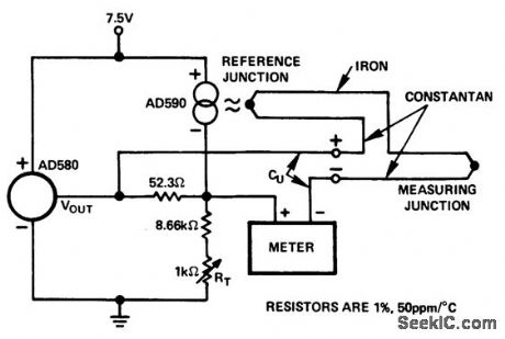
Cold junction compensation circuit for type J thermocouple(courtesy AnalogDevices,inc.). (View)
View full Circuit Diagram | Comments | Reading(1305)
One_quadrant_multiplication_using_a_DAC_IC10BC_D_A_converter_and_AM_452_op_amp
Published:2009/7/21 2:29:00 Author:Jessie
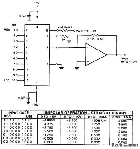
One-quadrant multiplication using a DAC-IC10BC D/A converter and AM-452 op amp. See coding table. With VIN connected to pin 16 the input impedance is low; with it connected to pin 15 the input impedance is high. The range is then 0 to -10 volts (courtesy Datel Systems, Inc.). (View)
View full Circuit Diagram | Comments | Reading(721)
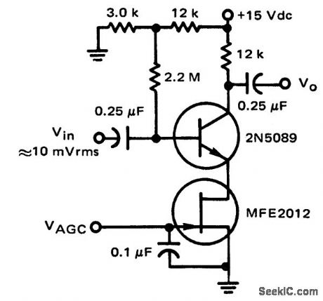
General_purpose_amplifier_with_FET_AGO_circuit
Published:2009/7/21 2:27:00 Author:Jessie
Voltage offset null circuit using an ECG915 operational amplifier. See basing diagram for supply connections. Supply is ±15 volts (courtesy GTE Sylvania Incorporated) (View)
View full Circuit Diagram | Comments | Reading(884)
NE602_LOCAL_OSCILLATOR_CIRCUITS
Published:2009/7/21 2:27:00 Author:Jessie


The local oscillator for the NE602 can take the form of either a crystal-controlled (a through d) or a resonant-tank circuit(e and ƒ). (View)
View full Circuit Diagram | Comments | Reading(3718)
Voltage_offset_null_circuit_using_an_ECG915_operational_amplifier
Published:2009/7/21 2:26:00 Author:Jessie
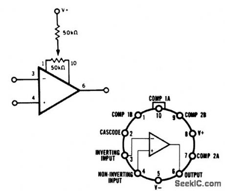
Voltage offset null circuit using an ECG915 operational amplifier. See basing diagram for supply connections. Supply is ±15 volts (courtesy GTE Sylvania Incorporated) (View)
View full Circuit Diagram | Comments | Reading(639)
SPARK_GAP_OSCILLATOR
Published:2009/7/21 2:25:00 Author:Jessie

A high-voltage current-limiting transformer (T1) supplies power to the basic LC tuned circuit. As C1 charges to near the transformer's maximum output voltage, the spark gap's air space breaks down, completing the circuit between the inductor and capacitor, L1 and C1. The tremendous inductive kick in the circuit is caused by the inductive field collapse when the spark gap shorts out the LC series circuit. The LC tuned circuit oscillates in a very broadband manner. (View)
View full Circuit Diagram | Comments | Reading(1821)
MMIC_AMPLIFIER_OSCILLATOR
Published:2009/7/21 2:24:00 Author:Jessie

The figure shows a basic oscillator circuit using an MMIC amplifier. (View)
View full Circuit Diagram | Comments | Reading(643)
Pulse_amplifier_using_an_MC1545G_for_applications_in_radar_IFs_pulse_width_modulation_and_pulse_amplitude_modulation_systems
Published:2009/7/21 2:20:00 Author:Jessie
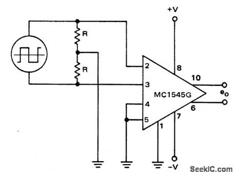
Pulse amplifier using an MC1545G for applications in radar IFs, pulse width modulation and pulse amplitude modulation systems (courtesy Motorola Semiconductor Products Inc.). (View)
View full Circuit Diagram | Comments | Reading(1725)
Voltage_controlled_amplifier_using_an_AD534_mulf_plier_divider_chip
Published:2009/7/21 2:39:00 Author:Jessie
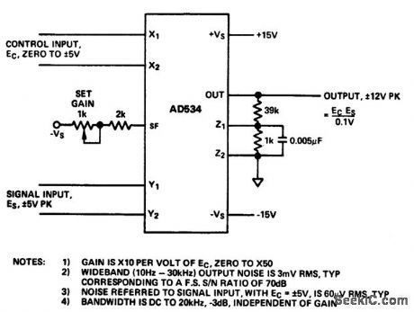
Voltage-controlled amplifier using an AD534 mulf plier/divider chip (courtesy Analog Devices, Inc.). (View)
View full Circuit Diagram | Comments | Reading(745)
HIGH_STABILITY_OSCILLATORS
Published:2009/7/21 2:39:00 Author:Jessie


These three high-stability oscillator circuits show the minor, but significant, differences between them: (a) Gouriet-Clapp oscillator with series resonance; (b) Seller low-C Colpitts oscillator with parallel resonance; (c) the Vackar oscillator, in which the ratios C2.Vc and C1:Cx should both be about 1:6. (View)
View full Circuit Diagram | Comments | Reading(854)
1296_MHz
Published:2009/7/21 2:38:00 Author:Jessie

Can be used as signal source for receiver adjustment and antenna testing, or as minibeacon on 1296 MHz. 48-MHz oscillator and clipper feed 144 MHz to 1N914 diode which multiplies frequency by 9. Half-wavelength strip line tank L3-C2 rejects other harmonics. Shorting link below RFC3 is removed for measuring code Current.-A 1296-MHz Signal Source, QST, March 1977, p 26. (View)
View full Circuit Diagram | Comments | Reading(2564)
ACCURATE_RING_OSCILLATOR
Published:2009/7/21 2:37:00 Author:Jessie


Four square-wave outputs can be produced with a single IC using this simple circuit setup. It takes advantage of the tightly controlled propagation delay of the LTC1520 quad line receiver to pro-duce a stable set of output waveforms. The circuit as shown uses all four comparator stages to de-liver quadrature output waveforms (90° phase increments). Because tPLH/tPLH skew (the difference between low-to-high and high-to-low propagation delays) is typically only 500 ps, the waveforms have duty factors that are very close to 50 percent. Channel-to-channel skew is usually only 400 ps, holding phase error between outputs to around 5°. An eight-phase oscillator (with 45° phase incre-ments) can be constructed by inverting φ 1 to φ (4 through another four LTC1520 comparators. It is also possible to build two-phase and three-phase ring oscillators by using two- and three-comparator sections, respectively. Just be sure that an odd number of inversions are around the loop, otherwise, the oscillator becomes a latch! Each LTC1520 input has a Thevenin input resistance of ±18 kΩ to 2/3 Vcc For a more accurate 50-percent duty factor, the dc threshold should be biased closer to 1/2 Vcc. This is easily done by connecting an external resistor divider to pull the switching threshold near 1/2 Vcc as is done with R1 and R2 in this figure. The measured temperature stability of the depicted oscillator is very good, normally varying less than 5 percent from 0° to 70℃ . (View)
View full Circuit Diagram | Comments | Reading(836)
1_watt_noninverting_power_amplifier_using_an_MC1554_connected_to_a_single_supply
Published:2009/7/21 2:37:00 Author:Jessie
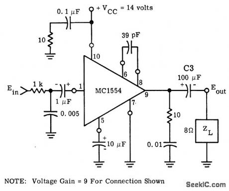
1-watt noninverting power amplifier using an MC1554 connected to a single supply. As shown voltage gain is nine (courtesy Motorola Semiconductor Products Inc.). (View)
View full Circuit Diagram | Comments | Reading(678)
Push_pull_monolithic_Darlington_amplifier
Published:2009/7/21 2:36:00 Author:Jessie

Push-pull monolithic Darlington amplifier (courtesy Motorola Semiconductor Products Inc.). (View)
View full Circuit Diagram | Comments | Reading(1217)
FM_SIGNAL_GENERATOR_OR_WOBBULATOR
Published:2009/7/21 2:36:00 Author:Jessie

With sine-wave input, RCA CA3046 transistor array connected as VCO can be used as low-distortion FM signal generator. With sawtooth input, same arrangement serves as wobbulator. Increasing size of timing capacitor reduces op-erating frequency, permitting use down to audio frequencies as voltage-controlled oscillator in electronic organ.-J. L. Linsley Hood, Linear Voltage Controlled Oscillator, Wireless World, Nov, 1973, p 567-569. (View)
View full Circuit Diagram | Comments | Reading(2455)
ALIGNMENT_OSCILLATOR
Published:2009/7/21 2:35:00 Author:Jessie

With 500-kHz crystal, output can be used as 5-kHz markers in sweep alignment procedure If SN7490P decade dividers are omitted and 455-kHz crystal is chosen, TTL circuit can be used to supply low IF value used by some receivers Circuit will oscillate up to several megahertz-J Carr, VHF FM Receiver Alignment Techniques, Ham Radio, Aug 1975,p14-22. (View)
View full Circuit Diagram | Comments | Reading(735)
GATE_DIP_OSCILLATOR
Published:2009/7/21 2:35:00 Author:Jessie

This dip oscillator, based on the classic vacuum-tube circuit, is very useful for checking tuned circuits and antennas, and is a valuable tool for the RF experimenter. Coil forms are 1/2-in diameter plastic tubing. (View)
View full Circuit Diagram | Comments | Reading(898)
NE602_AM_MODULATED_OSCILLATOR_CIRCUIT
Published:2009/7/21 2:32:00 Author:Jessie

By using an MC-1350P modulator IC, the output of the NE602 can easily be amplitude -modulated. (View)
View full Circuit Diagram | Comments | Reading(2197)
Vector_computer_using_one_AD531_multiplier_divider_and_two_AD741_op_amps
Published:2009/7/21 2:32:00 Author:Jessie
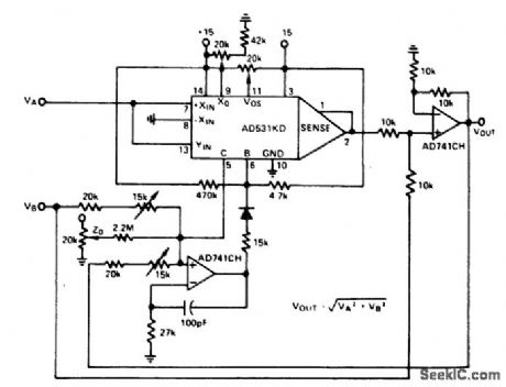
Vector computer using one AD531 multiplier/divider and two AD741 op amps. The circuit derives the square root of the sum of the squares (courtesy Analog Devices, Inc.). (View)
View full Circuit Diagram | Comments | Reading(1359)
Programmable_gain_noninverting_amplifier_with_selectable_inputs
Published:2009/7/21 2:31:00 Author:Jessie
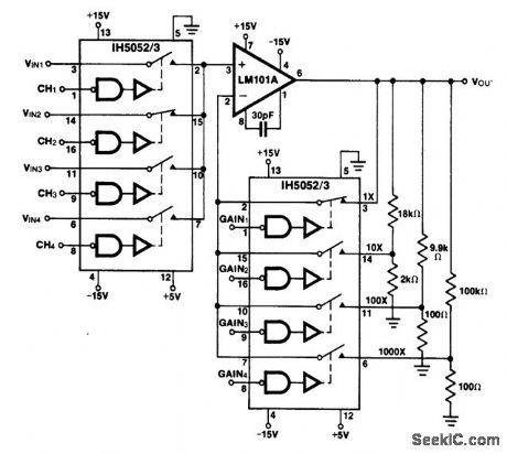
Programmable gain noninverting amplifier with selectable inputs. The IH5052/53 chips are 16-pin DIP CMOS analog gates (courtesy Intersil, Inc.). (View)
View full Circuit Diagram | Comments | Reading(731)
| Pages:951/2234 At 20941942943944945946947948949950951952953954955956957958959960Under 20 |
Circuit Categories
power supply circuit
Amplifier Circuit
Basic Circuit
LED and Light Circuit
Sensor Circuit
Signal Processing
Electrical Equipment Circuit
Control Circuit
Remote Control Circuit
A/D-D/A Converter Circuit
Audio Circuit
Measuring and Test Circuit
Communication Circuit
Computer-Related Circuit
555 Circuit
Automotive Circuit
Repairing Circuit