
Circuit Diagram
Index 944
FEEDBACK_REDUCES_DRIFT
Published:2009/7/20 21:54:00 Author:Jessie

FET Q2 serves as buffer for hold capacitor C1, minimizing droop error. Switching transistorQ1 is placed in feed-back loop. A1 serves as input signal buffer and as driver for Q1 and C1. When sample line is raised to +15 V by control pulse, D1 is reverse-biased and a, is turned on C1 now charges until output terminal reaches equilibrium with input (so A1 is tracking input). When sample pulse goes low, feedback loop of A1 is opened; output of A1 stays at voltage last sampled since C1 retains its charge and Q2 buffers this voltage while presenting it to output. Optional voltage follower can be used if more output current is needed to feed low-impedance load.-W. G. Jung, IC 0p-Amp Cookbook, Howard W. Sams, Indianapolis, IN, 1974, p 198-200. (View)
View full Circuit Diagram | Comments | Reading(654)
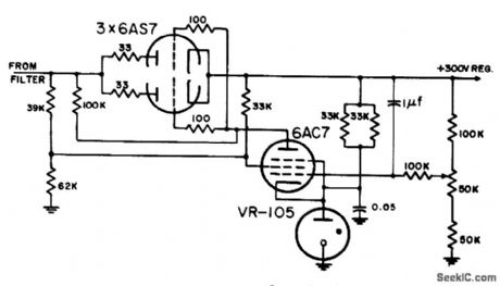
NEGATIVE_OUTPUT_300_V_REGULATOR
Published:2009/7/20 21:54:00 Author:Jessie
Operation is comparable to corresponding positive-output circuit.-NBS, Handbook Preferred Circuits Navy Aeronautical Electronic Equipment, Vol. 1, Electron Tube Circuits, 1963, p N2-5. (View)
View full Circuit Diagram | Comments | Reading(723)
COLOR_DEMODULATOR
Published:2009/7/20 21:54:00 Author:Jessie

Uses two 6JH8 sheet beam lubes as red and blue luminance demodulators. Balanced outputs of both polarities on plates of tubes eliminate need for additional phase inverter stages to recover green luminance signal-Color Demodulator Uses Beam Switching Tubes, Electronics, 34:36, p 30-31. (View)
View full Circuit Diagram | Comments | Reading(1049)
3_digit_ISUP2_SUPL_DPM_with_LCD_interface
Published:2009/7/20 21:53:00 Author:Jessie

3-digit I2L DPM with LCD interface (courtesy Analog Devices, Inc.). (View)
View full Circuit Diagram | Comments | Reading(575)
NEGATIVE_OUTPUT_152_V_REGULATOR
Published:2009/7/20 21:53:00 Author:Jessie

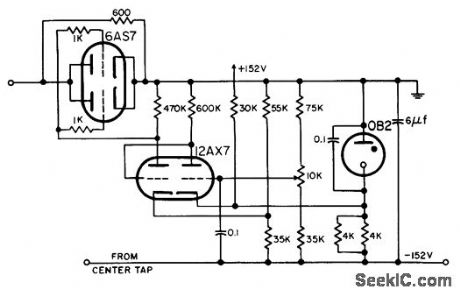
Operation is comparable to corresponding positive-output circuit.-NBS, Handbook Preferred Circuits Navy Aeronautical Electronic Equipment, Vol. 1, Electron Tube Circuits, 1963, p N2-5. (View)
View full Circuit Diagram | Comments | Reading(639)
CHROMA_CONIRQL_AND_COLOR_KILLER
Published:2009/7/20 22:06:00 Author:Jessie

Uses amplifier burst as reference to determine amount of bias on 6rst stage of chromo amplifier. If burst amplifier falls below certain level, color killer voltage cuts off chromo amplifier automatically.-D. Bray, Solid tale Makes Debut in Big-Screen Color Tv, Electronics, 39:8, p 99-105. (View)
View full Circuit Diagram | Comments | Reading(889)
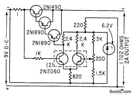
DARLINGTON_TRANSISTOR_SERIES_REGULATOR
Published:2009/7/20 22:05:00 Author:Jessie
Integrated transistor and zener diode in reference amplifer act with 2N2795 Darlington transistor to hold 50-ma output to within less than 0.001% of 12 v over 10% variation in a-c line voltage.-T. P. Sylvan, New Device Simplifies Power Supply Design, Electronics, 36:20, p 39-43. (View)
View full Circuit Diagram | Comments | Reading(880)
Sawtooth_generator_with_positive_going_ramp_using_a_zener_and_PNPN_diode
Published:2009/7/20 22:05:00 Author:Jessie

Sawtooth generator with positive-going ramp using a zener and PNPN diode (courtesy Motorola Semiconductor Products Inc.). (View)
View full Circuit Diagram | Comments | Reading(1249)
COLOR_SYNC_SEPARATOR
Published:2009/7/20 22:04:00 Author:Jessie

Trcansistorized version eliminates noise from horizontal sync pulses and isolates sync +tom video information. Noise theshold is established by voltage divider in emitter circuit of Q16.-D. Bray, Solid State Makes Debut in Big-Screen Color Tv, Electronics, 39:8, p 99-105.
(View)
View full Circuit Diagram | Comments | Reading(829)
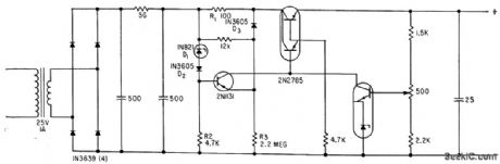
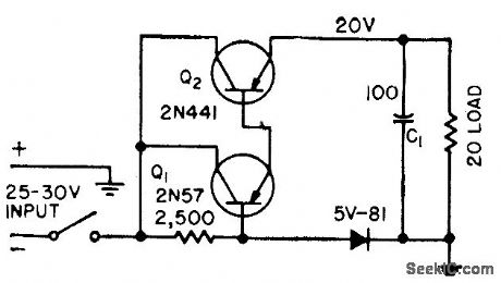
REFERENCE_AMPLIFIER_TESTS_POWER_SUPPLY_STABILITY
Published:2009/7/20 22:03:00 Author:Jessie

Integrated transistor and tenor diode serve as reference amplifier for testing effects of temperature on output voltage. After amplifier is heated or cooled, voltage divider is adjusted to restore initial collector current, and change in reference voltage is read from voltage divider scale to within 1 my.-T. P. Sylvan, New Device Simplifies Power Supply Design, Electronics, 36:20, p 39-43. (View)
View full Circuit Diagram | Comments | Reading(565)
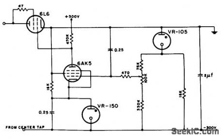
PENTODE_WITH_RIPPLE_SUPPRESSION
Published:2009/7/20 22:02:00 Author:Jessie
Screen is fed jointly from regulated and unregulated sides of supply, to reduce ripple. Plate load is low (100,000 ohms), providing good frequency response but increasing current fluctuations in VR-105.-NBS, Handbook Preferred Circuits Navy Aeronautical Electronic Equipment, Vol. 1, Electron Tube Circuits, 1963, p N2-2. (View)
View full Circuit Diagram | Comments | Reading(1475)
SOUND_I_F_FOR_COLOR_TV
Published:2009/7/20 22:01:00 Author:Jessie

Uses three transislor stages und Foster-Seeley discriminotor to give audio output of 1 v peak to peak. -D. Bray, Solid State Makes Debut in Big Screen Color Tv, Electronics, 39:8, p 99-105.
(View)
View full Circuit Diagram | Comments | Reading(775)
TWO_COLOR_TV
Published:2009/7/20 22:00:00 Author:Jessie

Picture is viewed on half-silvered mirror that combines images of red and green 14-inch picture tubes. Receiver circuits accept standard NTSC color. signal. Chief drawback is narrow angle of vision.-K. Hashimoto, Color TV Based on Land Theory uses Two Single-Gun Tubes, Electronics, 35:38, p 54-55. (View)
View full Circuit Diagram | Comments | Reading(917)
VOLTAGE_TUNABLE_MAGNETRON_FILAMENT_SUPPLY
Published:2009/7/20 22:00:00 Author:Jessie
Voltage drop across 1-ohm resistor, proportional to output current, is compared with fixed reference and held constant by series pass element.-S. Prigozy, Designing Special Power Supplies for Voltage-Tunable Oscillators, Electronics, 35:44, p 48-50. (View)
View full Circuit Diagram | Comments | Reading(837)
SIMPLE_SERIES_REGULATOR
Published:2009/7/20 21:59:00 Author:Jessie

Satisfactory for power supplies that are not subjected to shorted, capacitive, or suddenly increased loads. Any capacitance C1 at load must be charged through Q2, so entire supply voltage appears across Q2 before C1 starts charging. If initial charging current exceeds limits of Q2, it will be damaged immediately or become unstable.-H. D. Ervin, Transistor Power Supply has Overload Protection, Electronics, 31:25, p 74-75. (View)
View full Circuit Diagram | Comments | Reading(988)
Programmable_triangle_square_wave_function_generator
Published:2009/7/20 21:58:00 Author:Jessie

Programmable triangle/square-wave function generator. A1 and A2 are AD301 op amps. The peak-to-peak amplitude of both waveforms is approximately 15 volts (courtesy Analog Devices, Inc.). (View)
View full Circuit Diagram | Comments | Reading(649)
FRENCH_COLOR_TV_CHROMINANCE
Published:2009/7/20 21:58:00 Author:Jessie
SECAM system uses time multiplexing of two chrominance signals, transmitted sequentially, with one-line memory in receiver circuit.-R. Chaste, P. Cassagne, and M. Colas, Sequential Receivers for French Color Tv System, Electronics, 33:19, p 57-60. (View)
View full Circuit Diagram | Comments | Reading(1336)
107_MHz_IF_amplifier_using_a_3N204_dual_gate_MOSFET
Published:2009/7/20 22:21:00 Author:Jessie
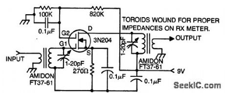
10.7 MHz IF amplifier using a 3N204 dual-gate MOSFET (courtesy Texas Instruments Incorporated). (View)
View full Circuit Diagram | Comments | Reading(1921)
COLOR_VIDEO_I_F
Published:2009/7/20 22:21:00 Author:Jessie
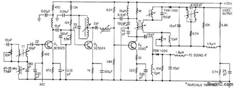
Three-stage amplifier has forward agc on first stage Q1. Sound trap at 41.25 Mc before detection prevents 900-Mc beat between color subcarrier and sound carrier. -D. Bray, Solid State Makes Debut in Big-Screen Color Tv, Electronics, 39:8, p 99- 105. (View)
View full Circuit Diagram | Comments | Reading(787)
105_MHz_to_107_MHz_converter_using_a_3N225_dual_gate_MOSFET
Published:2009/7/20 22:19:00 Author:Jessie
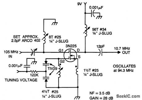
105 MHz to 10.7 MHz converter using a 3N225 dual-gate MOSFET (courtesyTexas Instruments Incorporated). (View)
View full Circuit Diagram | Comments | Reading(808)
| Pages:944/2234 At 20941942943944945946947948949950951952953954955956957958959960Under 20 |
Circuit Categories
power supply circuit
Amplifier Circuit
Basic Circuit
LED and Light Circuit
Sensor Circuit
Signal Processing
Electrical Equipment Circuit
Control Circuit
Remote Control Circuit
A/D-D/A Converter Circuit
Audio Circuit
Measuring and Test Circuit
Communication Circuit
Computer-Related Circuit
555 Circuit
Automotive Circuit
Repairing Circuit