
Circuit Diagram
Index 950
TRANSFORMER_COUPLED_SERIES_D_C_MODU_LATlON
Published:2009/7/21 Author:Jessie

Eliminates need for bulky modulation transformer and reduces envelope distortion when used in 27-Mc CB transmitter. Modulation power required is 0.35 mw. Chief disadvantage is that voltage source must be twice that of conventional collector-modulated transmitter.-B. Rheinfelder, Modulation Techniques for Transistorized A.M Transmitters, EEE, 11:7, p 54-57. (View)
View full Circuit Diagram | Comments | Reading(572)
F_M_P_M
Published:2009/7/20 23:59:00 Author:Jessie

Angle modulator gives phase modulation below 500 cps and frequency modulation above. Voltage-variable capacitor HC-7005 gives phase angle change of up to 25° at 1Mc.-A. C. Todd, P. Schuck, and H. M. Sachs, Using Voltage-Variable Capacitors in Modulator Design, Electronics, 34;3, p 56-59. (View)
View full Circuit Diagram | Comments | Reading(798)
TRANSISTOR_DIODE_PULSE_MODULATOR
Published:2009/7/20 23:58:00 Author:Jessie

Four-layer diodes used in series give rise times faster than turn-on limes of transistors, for pulse modulation of traveling-wave tubes and other devices al repetition rates up to 100 kc, with 5-microsec pulses and 3-mkrosec pulse spacings.-E. H. Heckman, Three New Approaches to Pulse Modulation, Electronics, 36:18, p 62-64. (View)
View full Circuit Diagram | Comments | Reading(706)
TRANSFORMER_COUPLED_COLLECTOR_MODU__LATED_TRANSMITTER
Published:2009/7/20 23:57:00 Author:Jessie

Widely used in a-m citizen's band (27-mc) transmitters. Modulation amplifier should be adjusted for dipping at 300-mw level, with passband from 300 to 3,000 cps. Input of 0.6 my will pro vide rated output of 780 mw at 70 db gain Large modulation transformer is required.- B. Rheinfelder, modulation Techniques for Transistorized A.M Transmitters, EEE, 11:7, p 54-57. (View)
View full Circuit Diagram | Comments | Reading(767)
CAPACITOR_BALANCED_SSB
Published:2009/7/20 23:56:00 Author:Jessie
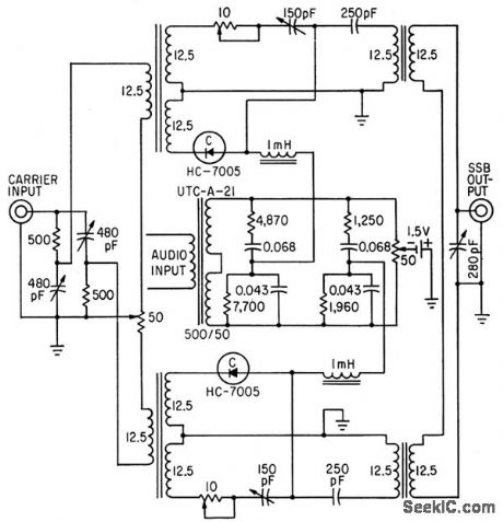
Output varies linearly with input over signal range of 0 to 4.5 V. Undesired sideband is suppressed 26 db at balance.-A. C. Todd, R P. Schuck, and H. M. Sachs, Using Voltage-Variable Capacitors in Modulator Design, Electronics, 34:3, p 56-59. (View)
View full Circuit Diagram | Comments | Reading(788)
4_channel_analog_data_selector
Published:2009/7/21 2:02:00 Author:Jessie
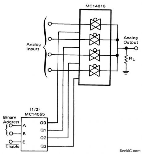
4-channel analog data selector (courtesy Motorola Semiconductor Products Inc.). (View)
View full Circuit Diagram | Comments | Reading(1371)
PRECISION_45_MHz_FM_FOR_TV_IF
Published:2009/7/21 2:02:00 Author:Jessie


Translation loop made from Signetics 561N and 562N PLLs produces 4.5-MHz signal with deviation of ±25 kHz, using 4.400-MHz crystal to control reference frequency. Modulation frequency is 400Hz. - Signetics Analog Data Manual, Signetics.Sunnyvale ,CA,1977,p843-845. (View)
View full Circuit Diagram | Comments | Reading(623)
Capacitor_discharge_SCR_ignition_system
Published:2009/7/21 1:59:00 Author:Jessie
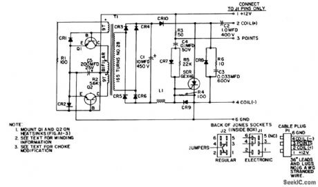
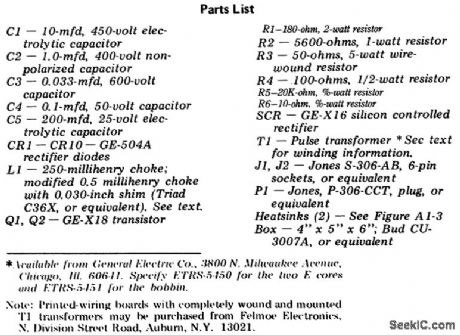
Capacitor discharge SCR ignition system. The circuit draws less than 1 ampere at high RPM (courtesy General Electric Company). (View)
View full Circuit Diagram | Comments | Reading(2587)
15_Hz_TO_40_kHz_IN_FOUR_RANGES
Published:2009/7/21 1:59:00 Author:Jessie

Tunable wide-range Wien-bridge audio oscillator is switched to cover 15-200 Hz, 150-2000 Hz, 1.5-20 kHz, and 3-40 kHz. U1 is high-input-impedance opamp in bridge circuit using thermistor as nonlinear feedback element. C1 is adjustable in series branch of bridge to compensate for capacitance (about 10pF) of ungrounded common terminal of dual tuning capacitor. Use ±15V dual regulated supply.-H. Olson, Integrated-Circuit Audio Oscillator, Ham Radio, Feb. 1973, p 50-54. (View)
View full Circuit Diagram | Comments | Reading(954)
100_kHz_CRYSTAL
Published:2009/7/21 1:56:00 Author:Jessie

Drives JK or RS flip-flops to provide markers at 10-kHz or 20-kHz intervals for calibrating transmitter, receiver, or transceiver. D1 and D2, used to stabilize output, can be eliminated if desired; R5 and R6 are then grounded directly. Transistor and diode types are not critical.-G. F. Moynahan, An Improved Crystal Calibrator Using Solid-State Techniques, CQ, May 1972, p 18 and 20. (View)
View full Circuit Diagram | Comments | Reading(1396)
FREQUENCY_STANDARD
Published:2009/7/21 1:54:00 Author:Jessie

Uses high-performance TTL ICs operating from regulated 5-V supply furnishing 260 mA, connected to point X. Provides choice of 18 precision frequencies if all ICs are used, or 8 marker frequencies if only upper three ICs are used. Adjustable level control permits matching output of frequency calibrator to incoming signals such as from WWV, or turning full on for strong, clear markers.HEP715 oscillator transistor is coupled to TTL by HEP50 transistor. 7493 binary dividers U1 and U5 divide by factor of 2, with 7490 decade dividers making up remainder of logic. Reset pins 2 and 3 control operation of logic, either with S1 or with progressively shorted contacts of rotary switch S2. Crystal should be ordered for 0.0005% tolerance, F-700 or SP7.P holder, 32-pF load, and 4 MHz at room temperature.-B. Kelley, Universal Frequency Standard, Ham Radio, Feb. 1974, p 40-47. (View)
View full Circuit Diagram | Comments | Reading(835)
Push_pull_discrete_Darlington_amplifier
Published:2009/7/21 1:54:00 Author:Jessie
Push-pull discrete Darlington amplifier (courtesy Motorola Semiconductor Products Inc.). (View)
View full Circuit Diagram | Comments | Reading(3364)
1_watt_noninverting_power_amplifier_for_split_power_supply_operation_using_an_MC1554
Published:2009/7/21 1:52:00 Author:Jessie

1-watt noninverting power amplifier for split power supply operation using an MC1554. As shown voltage gain is nine (courtesy Motorola Semiconductor Products Inc.). (View)
View full Circuit Diagram | Comments | Reading(576)
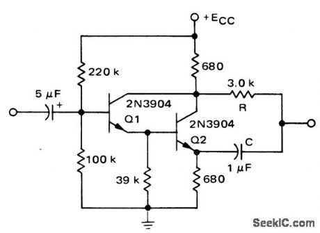
Multiplier_with_discrete_level_shift
Published:2009/7/21 1:50:00 Author:Jessie
Multiplier with discrete level shift (courtesy Motorola Semiconductor Products Inc.). (View)
View full Circuit Diagram | Comments | Reading(773)
30_kHz_MARKERS_FOR_2_METER_FM
Published:2009/7/21 1:47:00 Author:Jessie

Crystal is placed in loop of standard TTL MVBR, Circuit is modified so 32-pF parallel-mode unit will work into effective load of 32 pF. Series 220-pF capacitor raises crystal frequency enough to permit accurate frequency adjustment by trimmer. Oscillator output is fed to two decade dividers; output of second decade IC3 is 30-kHz square wave with 20% duty factor, coinciding with standard 2-meter FM channels. Regulated sup-ply is 5 VDC at 110 mA.-G. E. Zook, Channel Marker Generator, CQ, April 1972, p 41-42. (View)
View full Circuit Diagram | Comments | Reading(695)
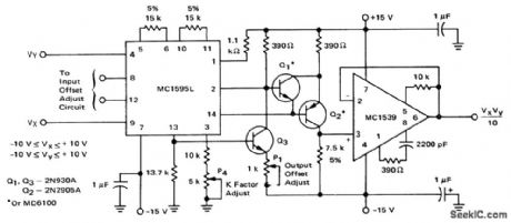
Multiplier_circuit_using_an_MC1595
Published:2009/7/21 1:47:00 Author:Jessie
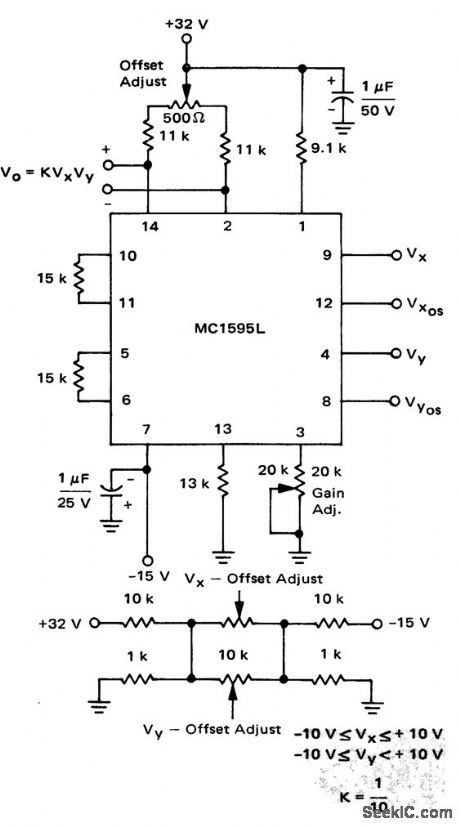
Multiplier circuit using an MC1595 (courtesy Motorola Semiconductor Products Inc.). (View)
View full Circuit Diagram | Comments | Reading(1230)
WAVEFORM_SYNTHESIZER
Published:2009/7/21 1:45:00 Author:Jessie

Values of weighting resistors connected to inputs of multiplexer chips determine waveform of analog output. CD4024 binary counter sequences multiplexers through all states at 16 times fundamental frequency of desired waveform. Active filter using 741 opamp removes components of sampling frequency. For near-approximation to sine wave, weighting resistors range from about 15Kto 425K.-J. R. Tracy, CMOS Circuits Generate Arbitrary Periodic Waveforms, EDN Magazine, Aug. 20, 1973, p 86-87. (View)
View full Circuit Diagram | Comments | Reading(1302)
Divider_with_digitally_controlled_gain
Published:2009/7/21 2:31:00 Author:Jessie
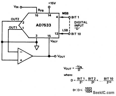
Divider with digitally controlled gain (courtesy Analog Devices, Inc.). (View)
View full Circuit Diagram | Comments | Reading(709)
32_kHz_DMOS_OSCILLATOR
Published:2009/7/21 2:31:00 Author:Jessie

Capacitors C1 and C2 and the crystal form a π section that causes a phase shift of 180°. Circuit IC1 is an inverter, which also causes a phase shift of 180°. Thus the total phase shift is 360°, which is necessary if the oscillations are to be sustained. (View)
View full Circuit Diagram | Comments | Reading(643)
OPERATIONAL_TRANSCONDUCTANCE_AMPLIFIER_OSCILLATOR
Published:2009/7/21 2:30:00 Author:Jessie

The only components in the simple circuit shown are a CA3048 OTA, a feedback resistor (R1), and a timing capacitor (C1). The output frequency is approximately given by:
ƒo≈1/(2πR1C1)
Timing resistor R1 should be from 1 to 3.9 MΩ .When R1 is of a greater value, the circuit some-Fig, 75-5 times stops oscillating, depending on the specific CA3048 used. (View)
View full Circuit Diagram | Comments | Reading(1098)
| Pages:950/2234 At 20941942943944945946947948949950951952953954955956957958959960Under 20 |
Circuit Categories
power supply circuit
Amplifier Circuit
Basic Circuit
LED and Light Circuit
Sensor Circuit
Signal Processing
Electrical Equipment Circuit
Control Circuit
Remote Control Circuit
A/D-D/A Converter Circuit
Audio Circuit
Measuring and Test Circuit
Communication Circuit
Computer-Related Circuit
555 Circuit
Automotive Circuit
Repairing Circuit