
Circuit Diagram
Index 947
105_MHz_to_107_MHz_mixer_using_a_TIS152_dual_gate_MOSFET
Published:2009/7/20 22:28:00 Author:Jessie
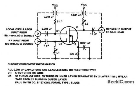
105 MHz to 10.7 MHz mixer using a TIS152 dual-gate MOSFET (courtesy Texas Instruments Incorporated). (View)
View full Circuit Diagram | Comments | Reading(2383)
CMOS_to_4_digit_incandescent_display_interface
Published:2009/7/20 22:27:00 Author:Jessie

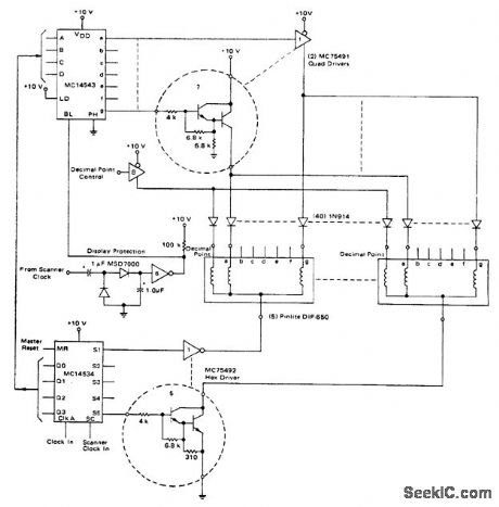
CMOS to 4-digit incandescent display interface(Courtesy Motorola Semiconductor Products Inc.). (View)
View full Circuit Diagram | Comments | Reading(622)
TACHOMETERLESS_SERVO
Published:2009/7/20 22:26:00 Author:Jessie
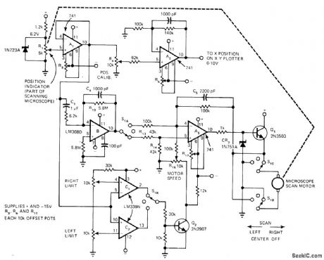
Developed to provide speed control for motor enclosed in such a way that tachometer cannot be used for feedback Position pot R1 and differentiator B substitute for tachometer in controlling rate of scanning-microscope eyepiece used for measuring CRT line width. Buffer A1 feeds X input of XY plotter through opamp A2, and also feeds differentiator B and limit-detector voltage comparator C1-C2. S1 switches A3 between inverting and noninverting operation each time scanning direction changes, to keep feedback negative.-H. F. Stearns, Differentiator and Position Pot Sub for Tachometer, EDN Magazine, Aug. 5, 1977, p 50-52. (View)
View full Circuit Diagram | Comments | Reading(999)
4_digit_CMOS_gas_discharge_display_
Published:2009/7/20 22:22:00 Author:Jessie
4-digit CMOS gas discharge display (courtesy Motorola Semiconductor Products Inc.). (View)
View full Circuit Diagram | Comments | Reading(969)
B_Y_DEMODULATOR
Published:2009/7/20 22:21:00 Author:Jessie
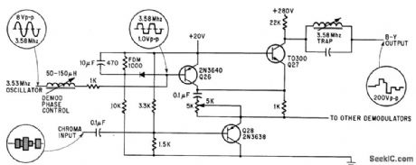
Used in transistorized color tv. R-Y demodulators are identical except for having different demodulation phase angle. –D. Bray, Solid State Makes Debue in Big-Screen Color Tv Electronics, 39:8, p 99-105. (View)
View full Circuit Diagram | Comments | Reading(825)
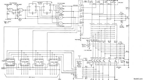
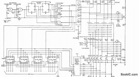
10_channel_scanning_logic_for_PF_scanner_monitor_receiver
Published:2009/7/20 22:44:00 Author:Jessie
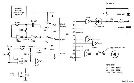
10-channel scanning logic for PF scanner/monitor receiver (courtesy Motorola Semiconductor Products Inc.). (View)
View full Circuit Diagram | Comments | Reading(1106)
DARLINGTON_PHASE_SHIFTER
Published:2009/7/20 22:43:00 Author:Jessie
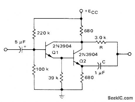
Basic 90°push-pull RC phase shifter using discrete transistors is connected as phase-splitting amplifier Used at output of follow-up pot in servo amplifier driving 115-V 60-Hz servomotor Supply is 28 V Motorola MPSA13 Darlington IC can be used if 39K resistor is omitted.-A, Pshaenich, Servo Motor Drive Amplifiers, Motorola,Phoenix,AZ,1972,AN-590. (View)
View full Circuit Diagram | Comments | Reading(1982)
Staircase_generator_2
Published:2009/7/20 22:43:00 Author:Jessie

Staircase generator. The number of steps is determined as follows: n=(C1 VBR)/(Iptp), where n is the number of steps, VBR is the breakdown voltage at the PNPN diode, IP is the pinchoff voltage of the 1N5283 and tp is the pulse width (courtesy Motorola Semiconductor Products Inc.). (View)
View full Circuit Diagram | Comments | Reading(651)
TTL_SERVO_CONTROL
Published:2009/7/20 22:42:00 Author:Jessie
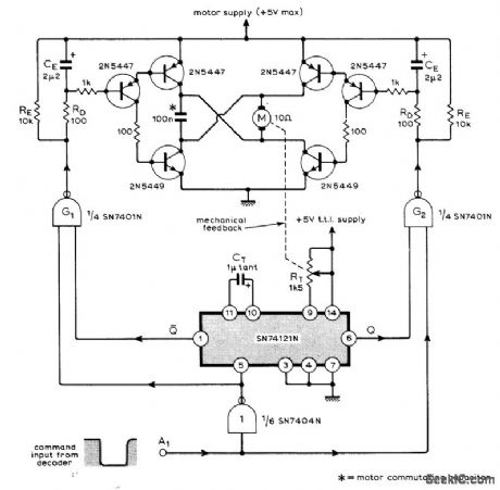
Used in nine-channel remote control system having nine identical servos fed by decoder at receiving end of data link. Variable-width pulse command from decoder is fed into TTL IC pulse-width comparator that feeds bridge-type motor drive. Command pulse controls both direction and duration of motor rotation. Article describes operation in detail and gives associated coder and decoder circuits.-M. F. Bessant, Multi-Channel Proportional Remote Control, Wireless World, Oct.1973, p 479-482. (View)
View full Circuit Diagram | Comments | Reading(2074)
27_MHz_AGC_able_self_oscillating_mixer_for_CB_operation_using_a_TIS148_dual_gate_MOSFET
Published:2009/7/20 22:42:00 Author:Jessie
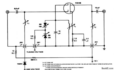
27 MHz AGC-able self-oscillating mixer for CB operation using a TIS148 dual gate MOSFET (courtesy Texas Instruments Incorporated). (View)
View full Circuit Diagram | Comments | Reading(850)
SERVO_DRIVE
Published:2009/7/20 22:40:00 Author:Jessie
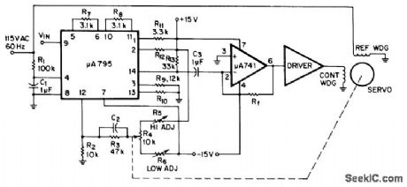
Combination of Fairchild μA795 multiplier and μA741 opamp generates AC error signal for driving two-phase servo-motor. Phase-shifted signal from R1-C1 is applied to input pin 4 of multiplier, DC signal input is applied to pin 9, and servo position signal goes to pin 12. Multiplier takes difference between signals on 9 and 12, multiplies this by signal on pin 4, and feeds resulting sine wave from pin 14 to opamp for amplification and transfer to servo driver. When servomotor action makes voltages on 9 and 12 equal, system is nulled.-Fairchild Linear IC Contest Winners, EEE Magazine, Jan. 1971, p 48-49. (View)
View full Circuit Diagram | Comments | Reading(1586)
27_MHz_to_107_MHz_mixerfor_CB_operation_using_a_TIS148_dual_gate_MOSFET
Published:2009/7/20 22:40:00 Author:Jessie
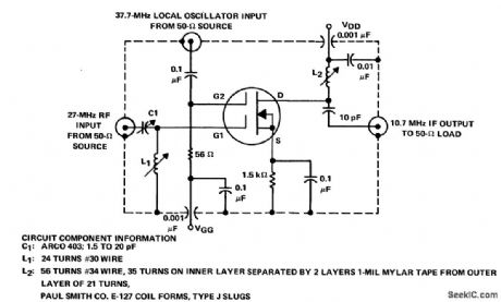
27 MHz to 10.7 MHz mixerfor CB operation using a TIS148 dual-gate MOSFET(courtesy Texas Instruments Incorporated). (View)
View full Circuit Diagram | Comments | Reading(1013)
Precision_ramp_generators_using_a_Datel_ADC_MC8B_16_pin_DIP
Published:2009/7/20 22:39:00 Author:Jessie

Precision ramp generators using a Datel ADC-MC8B 16-pin DIP. Pin functions of the ADC-MC8B are as follows: pin 1, ground; pin 2, logic select; pin 3, reset; Pin 4, strobe; pin5, bit8(LSB); pin6, bit7; pin 7, bit6; pin8, +Vcc; pin 9, bit 5; pin 10, bit4; pin 11, bit3; pin 12, bit2; pin 13, bit 1 (MSB); pin 14, analog output; pin 15, VREF input; pin 16, VREF output (courtesy Datel Systems, Inc.). (View)
View full Circuit Diagram | Comments | Reading(618)
DUAL_OPAMP_PREAMP
Published:2009/7/20 22:38:00 Author:Jessie
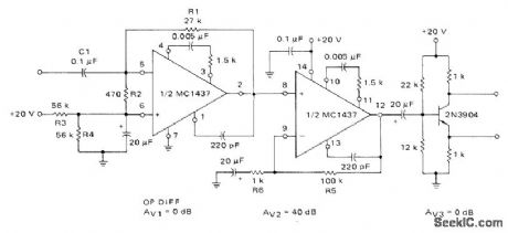
First section of Motorola MC1437 dual opamp is connected as operational differentiator driving direct-coupled noninverting opamp. Single-ended output is converted to push-pull by following phase-split-ting amplifier for driving power amplifier of 115-V 60-Hz servomotor.-A. Pshaenich, Servo Motor Drive Amplifiers, Motorola, Phoenix, AZ, 1972, AN-590. (View)
View full Circuit Diagram | Comments | Reading(1235)
Single_pulse_generator_using_an_SUS
Published:2009/7/20 22:37:00 Author:Jessie

Single pulse generator using an SUS. This circuit is useful in testing digital equipment. The output is a clean debounced pulse of 3 ms duration (courtesy Motorola Semiconductor Products Inc.). (View)
View full Circuit Diagram | Comments | Reading(729)
5_digit_incandescent_display
Published:2009/7/20 22:36:00 Author:Jessie
5-digit incandescent display (courtesy Motorola Semiconductor Products Inc.). (View)
View full Circuit Diagram | Comments | Reading(618)
900_MHz_BF_amplifier_using_a_3N225_dual_gate_MOSFET
Published:2009/7/20 22:35:00 Author:Jessie
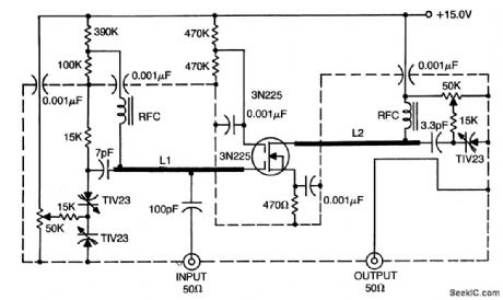
900 MHz BF amplifier using a 3N225 dual-gate MOSFET. Coils L1 and L2 consist of the leads of the 1 pF and 3 pF capacitors (courtesy Texas Instruments Incorporated). (View)
View full Circuit Diagram | Comments | Reading(732)
1_MHz_oscillator_using_the_MC1553_video_amplifier
Published:2009/7/20 23:06:00 Author:Jessie

1 MHz oscillator using the MC1553 video amplifier (courtesy Motorola Semiconductor Products Inc.). (View)
View full Circuit Diagram | Comments | Reading(561)
27_MHz_transmitter_for_CB_operation
Published:2009/7/20 23:05:00 Author:Jessie

27 MHz transmitter for CB operation. Power output is 3.5 watts minimum. Typical efficiency is 70%. Modulation can be±100%. Second harmonic suppression istypically 38 dB down, while third harmonicsuppression is 55 dB down. All coilsare on 1/4-inch forms with AWG #22 wire. Slugs are 1/4 by 3/8-inch J-types. Secondary windings are overwound on the bottom of the primary. L1 primary is 12 turns close wound, while the secondary is 2 turns. L2 primary is 18 turns close wound, while its secondary is 2 turns. L3 is 7 turns dose wound. L4 is 5 turns close wound (courtesy Motorola Semiconductor Products Inc.). (View)
View full Circuit Diagram | Comments | Reading(2618)
12_VDC_DRIVE
Published:2009/7/20 23:05:00 Author:Jessie
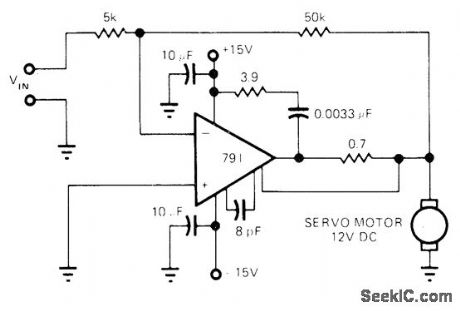
Circuit uses 791 power opamp in inverting configuration with gain of 10 for driving size 8 12-VDC servomotor in either direction. Article tells how to calculate heatsink requirements for opamp.-R. J. Apfel, Power Op Amps-Their Innovative Circuits and Pack-aging Provide Designers with More Options, EDN Magazine, Sept. 5, 1977, p 141-144, (View)
View full Circuit Diagram | Comments | Reading(906)
| Pages:947/2234 At 20941942943944945946947948949950951952953954955956957958959960Under 20 |
Circuit Categories
power supply circuit
Amplifier Circuit
Basic Circuit
LED and Light Circuit
Sensor Circuit
Signal Processing
Electrical Equipment Circuit
Control Circuit
Remote Control Circuit
A/D-D/A Converter Circuit
Audio Circuit
Measuring and Test Circuit
Communication Circuit
Computer-Related Circuit
555 Circuit
Automotive Circuit
Repairing Circuit