
Circuit Diagram
Index 958
TV_video_signal_processor_circuit
Published:2009/7/21 5:27:00 Author:Jessie

TV video signal processor circuit. The ECG1066 is a 16-pin DIP (courtesy GTE Sylvania Incorporated). (View)
View full Circuit Diagram | Comments | Reading(722)
_PWM_SERVO_AMPLIFIER
Published:2009/7/8 4:43:00 Author:May
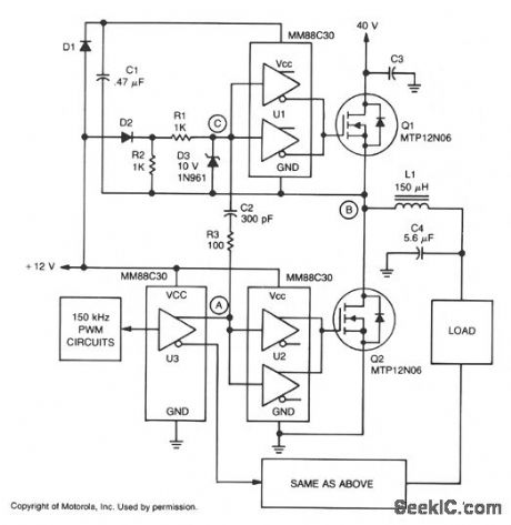
A major feature of the PWM servo amplifier is elimination of a pulse transformer. A 150 kHz pulse-width modulated signal is applied to U3, with its complementary outputs applied to identical circuits to drive the load. When point A increases, Q2 is on and point B is at ground potential. The VCC, for U1 is maintained through D1, and Q1 is held off by D2. When point A decreases,Q2 turns off, point C is pulled low by C2, which turns Q1 on. The time constant for R1, R3, and C2 can hold Q1 on just long enough to allow the voltage at point B to start rising. As point B rises, it charges C2 by forward biasing D3, maintaining point C low with respect to U1, and keeping Q1 turned on.
With point B at 40 V, D2 is off and point C is held low by R1 and R2, and VCC for U1 is maintained by the charge on C1. When point A increases again, Q2 again turns on, C2 pushes point C high, and turns Q1 off long enough to allow the voltage at point B to start falling. C2 is now discharged by reverse-biased D3, which keeps point C high with respect to U1, and keeps Q1 off. Once point B reaches ground potential, D1 again turns on, recharging C1, and maintaining VCC to U1. D2 also turns on and keeps Q1 off. (View)
View full Circuit Diagram | Comments | Reading(1156)
THERMOCOUPLE_AMPLIFIER
Published:2009/7/8 4:43:00 Author:May
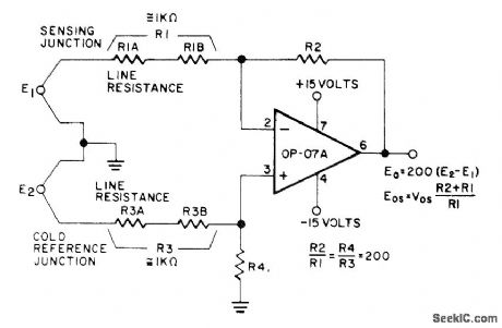
Precision Monolithics 0P-07A opamp has high common-mode rejection ratio and long-term accuracy required for use with thermocouples having full-scale outputs under 50 mV, frequently located in high-noise industrial environments. CMRR is 100 dB over full ±13 V range when ratios R2/R1 and R4/R3 are matched within 0.01'/0, Circuit is useful in many other applications where small differential signals from low-impedance sources must be accurately amplified in presence of large Gommon-mode voltages.—D.Soderquist and G Erdi, The op-07 Ultra-LowOffset voltage Op Amp-a Bipolar Op Amp That Challenges Choppers,Eliminates Nulling, Precision Monolithics, Santa Clara,CA,1975,AN-13,p 11.
(View)
View full Circuit Diagram | Comments | Reading(0)
Touch_switch_for_loads_up_to_180_watts
Published:2009/7/21 5:25:00 Author:Jessie
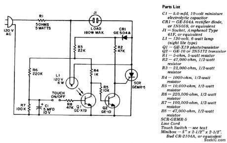
Touch switch for loads up to 180 watts. This circuit is good for turning on and off lights, TVs, stereos, etc. Q1 is a phototransistor (courtesy General Electric Company). (View)
View full Circuit Diagram | Comments | Reading(522)
PHOTODIODE_AMPLIFIER
Published:2009/7/8 4:43:00 Author:May

This circuit uses a CA5422 dual BiMOS microprocessor op amp. The bootstrap amplifiers minimize bias currents while maintaining electrostatic discharge protection. Additionally, the potentiometers and their associated resistors, R1 through R4, permit the user to trim bias currents to zero. (View)
View full Circuit Diagram | Comments | Reading(0)
The_ECG1070_16_pin_DiP_
Published:2009/7/21 5:24:00 Author:Jessie

The ECG1070 16-pin DiP (courtesy GTE Sylvania Incorporated). (View)
View full Circuit Diagram | Comments | Reading(701)
TV_video_signal_processor
Published:2009/7/21 5:23:00 Author:Jessie

TV video signal processor. The ECG 1070 is a 16-pin DIP (courtesy GTE Sylvania Incorporated). (View)
View full Circuit Diagram | Comments | Reading(678)
RMS_open_loop_voltage_compensator_regulator_for_application_requiring_large_conduction_angles
Published:2009/7/21 5:08:00 Author:Jessie
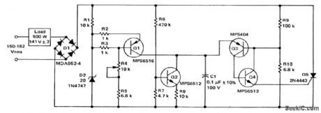
RMS open-loop voltage compensator (regulator) for application requiring large conduction angles. It provides an output 141 ±2 volts RMS at 500 watts for an input of 150 to 182 volts RMS (courtesy Motorola Semiconductor Products Inc.). (View)
View full Circuit Diagram | Comments | Reading(685)
Linear_TV_IF_amplifier_using_an_ECG_1080_chip
Published:2009/7/21 5:08:00 Author:Jessie

Linear TV IF amplifier using an ECG 1080 chip, which provides 46 dB powergain. Transformer T is 0.32 mm enamel wire with a center-tapped primary of eight tums close wound. The secondary is one tum of the same wire. The coil form diameter is 5.5 mm (courtesy GTE Sylvania Incorporated). (View)
View full Circuit Diagram | Comments | Reading(733)
Color_TV_chroma_demodulator_with_direct_output
Published:2009/7/21 5:07:00 Author:Jessie

Color TV chroma demodulator with direct output. The ECG1099 is a 14-pinDIP with tab,R-Y,B-Y, and G-Y output voltages are 12 volts,3.8 volts,and 1 volt peak to peak,respectively (courtesy GTE Sylvanic Incorporated) (View)
View full Circuit Diagram | Comments | Reading(861)
Triac_temperature_sensitive_heater_control
Published:2009/7/21 5:06:00 Author:Jessie

Triac temperature-sensitive heater control. This circuit can be modified as shown to control a motor with a constant load. As shown the circuit is for heating applications but can be used for cooling by interchanging RT and R2 (courtesy Motorola Semiconductor Products Inc.). (View)
View full Circuit Diagram | Comments | Reading(2323)
Time_dependent_light_dimmer
Published:2009/7/21 5:04:00 Author:Jessie

Time-dependent light dimmer. The circuit allows bright lights to slowly fade over a period of 15 to 20 minutes and permits loads up to 500 watts (courtesy General Electric Company). (View)
View full Circuit Diagram | Comments | Reading(703)
135_kHz_STRIP
Published:2009/7/8 4:41:00 Author:May

Developed for use in all-band VHF/UHF/S-band receiver. Operates from 12-Vsupply, connected to positive terminal of C11 through 100-ohm resistor.Articlee covers design and construction.-B. Hoisington,Building a 135 kHz 1-F Strip,73 Magazine,Sept 1975,p127-130 and 132. (View)
View full Circuit Diagram | Comments | Reading(1187)
DOUBLE_SIDEBAND_SUPPRESSED_CARRIER_MODULATOR
Published:2009/7/8 4:41:00 Author:May
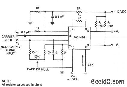
The basic current allows no carrier to be present in the output. By adding offsets to the carrier differential pairs, controlled amounts of carrier appear at the output. The amplitude becomes a function of the modulation signal-AM modulation.
(View)
View full Circuit Diagram | Comments | Reading(2031)
EQUALIZED_PREAMP_FOR_MAGNETIC_PHONOGRAPH_CARTRIDGES
Published:2009/7/8 4:41:00 Author:May

This circuit uses a CA3130 BiMOS op amp. Amplifier is equalized to RIAA playback frequency-response specif[cations. The circuit is useful as preamplifier following a magnetic tapehead. (View)
View full Circuit Diagram | Comments | Reading(1261)
BALANCED_MODULATOR
Published:2009/7/8 4:39:00 Author:May
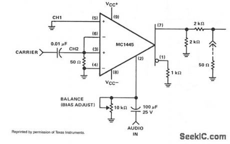
When the carrier level is adequate to switch the cross-coupled pair of differential amplifiers, the modulation signal, which has been applied to the gate, will be switched at the carrier rate, between the collector loads. When switching occurs, it will result in the modulation being multiplied by a symmetrical switching function. If the modulation gate remains in the linear region, only the first harmonic will be present. To balance the MC1445 modulator, equal gain must be achieved in the two separate channels. To remain in the linear region, the modulation input must be restricted to approximately 200 mV pk-pk. Because the gate bias point is sensitive to the amount of carrier suppression, a high-resolution, 10-turn potentiometer should be used. (View)
View full Circuit Diagram | Comments | Reading(0)
PULSE_WIDTH_MODULATOR
Published:2009/7/8 4:39:00 Author:May

In this application, the timer is connected in the monostable mode. The circuit is triggered with a continuous pulse train and the threshold voltage is modulated by the signal applied to the control voltage terminal at pin 5. This has the effect of modulating the pulse width as the control voltage varies. The figure shows the actual waveform generated with this circuit. (View)
View full Circuit Diagram | Comments | Reading(4044)
PULSE_POSITION_MODULATOR
Published:2009/7/8 4:38:00 Author:May

This application uses the timer connected for astable (free-running) operation, with a modulating signal again applied to the control voltage terminal. The pulse position varies with the modulating signal, since the threshold voltage and the time delay is varied. (View)
View full Circuit Diagram | Comments | Reading(1456)
TRANSISTOR_TESTING_SUPPLY
Published:2009/7/21 5:01:00 Author:Jessie
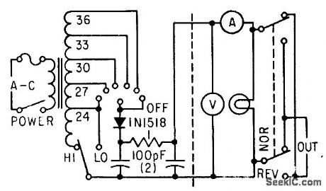
Six taps on transformer, plus range switch that transfers negative bus to 24-V tap, provide choice of nine constant outputs from 3 to 36 V d-c.-F. W. Kear, Laboratory Supply for Transistors, Electronics, 35:30, p 55-57. (View)
View full Circuit Diagram | Comments | Reading(603)
6_36_MHz_HARMONIC_GENERATOR
Published:2009/7/21 5:00:00 Author:Jessie

Phase locked loop is used with short-duration pulses from 1-MHz crystal reference oscillator to produce highly accurate harmonics SN74S00N Schottky U2 changes reference wave form to harmonic-rich 100-ns pulses for feed to 1N914 phase-detector diodes CR1 and CR2 Buffer U3 delivers output of 2N5140 VCO to diodes for phase compalison and phase-frequency output is fed to opamp U5 that locks VCO more tightly to reference-oscillator output by increasing its control of varactor, VCO frequency will then be harmoic of reference oscillator Meter used to monitor control voltage to varactor can have full-scale value of 100μA to 1mA, with its multiplier resistor adjusted to read 5 V at midscale.When opamp is capturing VCO, meter needle will flop from side to side but will return to midscale after lock is achieved. Article covers construction, tuning, and operation.-K. W. Robbins and J. R. True, Crystal-Controlled Harmonic Generator, Ham Radio, Nov. 1977, p 66-69. (View)
View full Circuit Diagram | Comments | Reading(1232)
| Pages:958/2234 At 20941942943944945946947948949950951952953954955956957958959960Under 20 |
Circuit Categories
power supply circuit
Amplifier Circuit
Basic Circuit
LED and Light Circuit
Sensor Circuit
Signal Processing
Electrical Equipment Circuit
Control Circuit
Remote Control Circuit
A/D-D/A Converter Circuit
Audio Circuit
Measuring and Test Circuit
Communication Circuit
Computer-Related Circuit
555 Circuit
Automotive Circuit
Repairing Circuit