
Circuit Diagram
Index 945
3_digit_ISUP2_SUPL_DPM_with_Beckman_gas_discharge_display
Published:2009/7/20 22:19:00 Author:Jessie

3-digit I2L DPM with Beckman gas discharge display (courtesy Analog Devices, Inc.). (View)
View full Circuit Diagram | Comments | Reading(660)
COLOR_BURST_AMPLIFIER
Published:2009/7/20 22:19:00 Author:Jessie
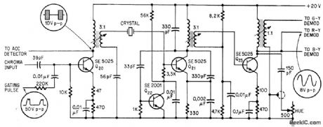
Burst amplifier Q20 and 3.58-Mc crystal oscillator Q21 are driven by output of 0rst stage of chroma amplifier of transistorized color tv. Amplifier burst locks oscillator frequency to subcarrier frequency required by color demodulators, and provides reference burst for automatic color control circuit.-D. Bray, Solid State Makes Debut in Big4creen Color Tv, Electronics, 39:8, p 99-105. (View)
View full Circuit Diagram | Comments | Reading(811)
Programmable_function_generator_with_square_and_triangular_wave_outputs
Published:2009/7/20 22:19:00 Author:Jessie

Programmable function generator with square and triangular wave outputs (courtesy Analog Devices, Inc.). (View)
View full Circuit Diagram | Comments | Reading(677)
COLOR_HOLD
Published:2009/7/20 22:18:00 Author:Jessie
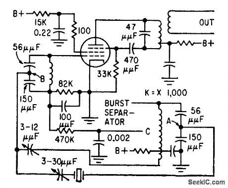
Uses passive fiber to separate color subcarrier frequency front sync burst, along with injection-locked oscillator that combines amplitude limiting and power amplification for direct drive of color demodulators.-I. N. Moth, Locked Oscillator for Color Tv, Electronics, 32:39, p 91-92. (View)
View full Circuit Diagram | Comments | Reading(800)
12_digit_CMOS_gas_discharge_display_
Published:2009/7/20 22:18:00 Author:Jessie

12-digit CMOS gas discharge display (courtesy Motorola Semiconductor Products Inc.). (View)
View full Circuit Diagram | Comments | Reading(588)
Staircase_generator
Published:2009/7/20 22:18:00 Author:Jessie

Staircase generator. The resistor array is switched to ground to generate binary or BCD weighted currents. The op amp converts these currents to an output voltage. Under reset condition the switches are off and the output is at ground. When a trigger is applied the output goes to VREF and generates a negative-going staircase of 256 levels for the 8240 or 100 level for the 8250. The time duration of each step is equal to the time base period, T = RC. The amplitude of the staircase can be varied by changing the input reference voltage. The stair-case can be stopped at any desired level by applying a disable signal to pin 14 (courtesy Intersil, Inc.). (View)
View full Circuit Diagram | Comments | Reading(0)
BALANCED_DIODE_COLOR_BURST_GATE
Published:2009/7/20 22:17:00 Author:Jessie
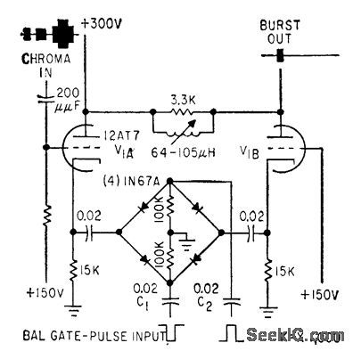
Used in automatic video-processing amplifier that instantly compensates for wide variations in color or monochrome input signal levels, to maintain output signal components al correct levels.-J. O. Schroeder, Holding Video Levels While Switching Studios, Electronics, 32:22, p 96-98. (View)
View full Circuit Diagram | Comments | Reading(789)
COLOR_AGC
Published:2009/7/20 22:17:00 Author:Jessie
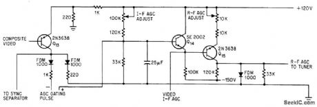
Supplies bias voltage to r-f and video i-f stages of color set using transistors in all but deflection and recliner stages, to maintain video output amplitude at about 3 v.-D. Bray, Solid State Makes Debut in Big-Screen Color Tv, Electronics, 39:8, p 99-105 (View)
View full Circuit Diagram | Comments | Reading(644)
107_MHz_to_455_kHz_mixer_for_CB_operation_using_a_TIS148_dual_gate_MOSFET
Published:2009/7/20 22:16:00 Author:Jessie
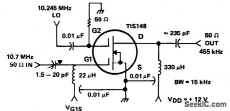
10.7 MHz to 455 kHz mixer for CB operation using a TIS148 dual-gate MOSFET (courtesy Texas Instruments Incorporated). (View)
View full Circuit Diagram | Comments | Reading(1775)
REFERENCE_OSCILLATOR_FOR_COLOR_TV_KLYSTRON
Published:2009/7/20 22:12:00 Author:Jessie
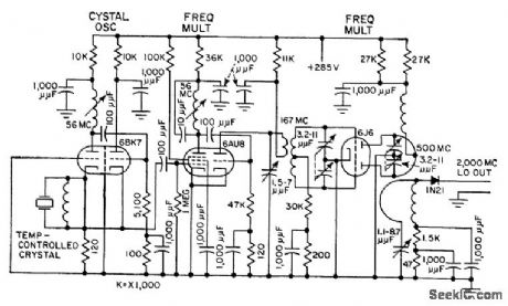
Used in afc system that locks 2,000-Mc klystron to crystal oscillator reference frequency. Receiving-tube multipliers provide 50 mw at 500 Mc, and silicon crystal diode quadruples this to give 0.25 mw ct 2,000 Mc. Used in mobile microwave relay system for color tv pickups.-T. G. Custin and J. Smith, Relay System Diplexes Audio and Color Video, Electronics, 31:25, p 64-67. (View)
View full Circuit Diagram | Comments | Reading(1425)
4_digit_direct_drive_LCD
Published:2009/7/20 22:11:00 Author:Jessie

4-digit direct drive LCD (courtesy Motorola Semiconductor Products Inc.). (View)
View full Circuit Diagram | Comments | Reading(0)
GLITCH_CANCELLATION
Published:2009/7/20 22:11:00 Author:Jessie
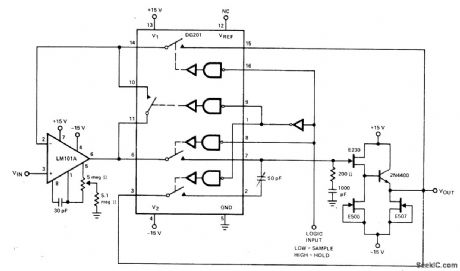
Fourth section of DG201 quad CM0S analog switch provides cancellation of coupled charges (glitches), to keep sample-and-hold offset below 5 mV over analog voltage range of -10 V to +10 V. Acquisition time is 25μs for opamp shown but can be im-proved by using faster-slewing opamp. Aperture time is typically 1 ps- Analog Switches and Their Applications, Silliconix, Santa Clara,CA,1976,p 7-68. (View)
View full Circuit Diagram | Comments | Reading(1428)
12_digit_TTL_multiplexed_planar_gas_discharge_display
Published:2009/7/20 22:10:00 Author:Jessie


12-digit TTL multiplexed planar gas discharge display (courtesy Motorola Semiconductor Products Inc.). (View)
View full Circuit Diagram | Comments | Reading(599)
LUMINANCE_AMPLIFIER
Published:2009/7/20 22:10:00 Author:Jessie
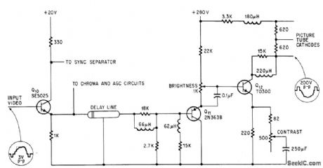
Provides bandwidth of 2 Mc, with 200.v output, for color set having transistors in all except defection and rectifier circuits. Brightness is controlled by shifting base bias voltage of Q12, and contrast by varying ac emitter impedance of Q12.-D. Bray, Solid State Makes Debut in Big-Screen Color Tv, Electronics, 39:8, p 99-105. (View)
View full Circuit Diagram | Comments | Reading(781)
INVERTING_SAMPLE_AND_HOLD
Published:2009/7/20 22:09:00 Author:Jessie

Total offset error can be adjusted to much less than 1 mV in 2N5545 FET-input opamp by using compensation circuit R3-C2-C3 with DG181 JFET analog switch. Switch operation occurs consistently at constant voltage, reducing aperture time jitter. Designed for high-speed sample-and-hold requirements.- Analog Switches and Their Applications, Siliconix, Santa Clara,CA,1976,p7-59. (View)
View full Circuit Diagram | Comments | Reading(702)
AUTOMATIC_CHROMA_CONTROL
Published:2009/7/20 22:09:00 Author:Jessie
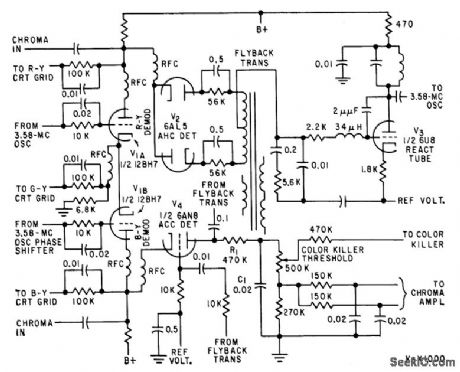
Improves stability of hue, saturation, noise, and pull in characteristics of received color tv signals. Low-frequency diode gate corrects subcarrier oscillator phase from synchronous demodulator signals and establishes signal level for a chromo control circuit.-Z. Wiencek, Automatic Controls for Color Television, Electronics, 32:20, p 58-59. (View)
View full Circuit Diagram | Comments | Reading(744)
Space_mark_generator_with_voltage_controlled_duty_cycle
Published:2009/7/20 22:09:00 Author:Jessie

Space mark generator with voltage-controlled duty cycle. Frequency is set by RE in the source circuit of Q1 (courtesy Motorola Semiconductor Products Inc.). (View)
View full Circuit Diagram | Comments | Reading(734)
AUTOMATIC_FINE_TUNING
Published:2009/7/20 22:08:00 Author:Jessie
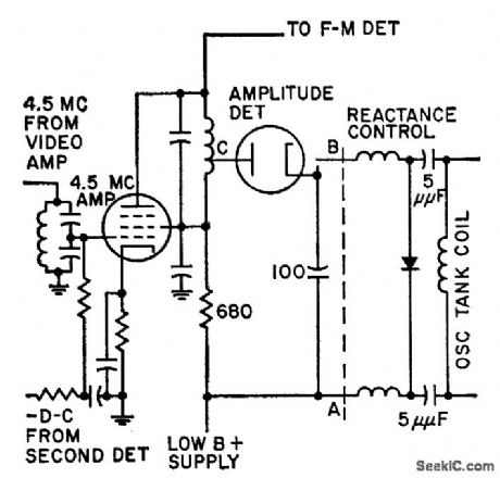
Amplitude of 4.5-Mc intercarrier sound signal controls sound-to-picture ratio to provide automatic lne tuning. Automatic control of beats between picture harmonics and sound carrier closely approximates manual tuning. Circuit is particularly valuable for remote control of color tv sets. -C. W. Bough, Jr., and L. J. Sienkiewicz, Sound Signal Tunes Tv Automatically, Electronics, 31:17, p 54-58. (View)
View full Circuit Diagram | Comments | Reading(717)
DERIVATIVE_SLOPE_SAMPLING
Published:2009/7/20 22:07:00 Author:Jessie

Analog derivative circuit forces voltage across C1 to follow slowly changing input signal. Current required to keep capacitor voltage equal to signal volt-age is proportional to rate of change of signal voltage. RCA 3033 FET-input opamp will work equally as well as Teledyne Philbrick 1421 shown. Careful selection of values for Rπ and C1 will set rate limit that will reject spikes.-R. E. Bober, This Derivative Circuit Handles Slowly Varying Signals, EDN Magazine, Jan. 20, 1976, p82. (View)
View full Circuit Diagram | Comments | Reading(730)
AFC_FOR_COLOR_TV_KLYSTRON
Published:2009/7/20 22:07:00 Author:Jessie
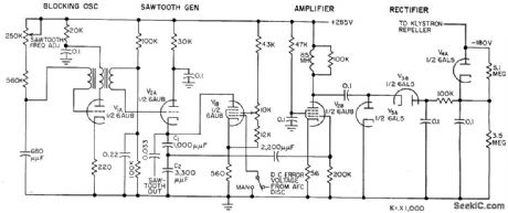
Used with visual f-m transmitter for microwave ralay. Klystron locks to crystal i-f difference frequency to provide required high degree of stability. Calibrated wavetrap modifies sawtooth waveshape of afc to provide internal frequency monitoring. -T .-G. Custin and J. Smith, Relay System Diplexes Audio and Color Video, Electronics, 31:25, p 64-67 (View)
View full Circuit Diagram | Comments | Reading(817)
| Pages:945/2234 At 20941942943944945946947948949950951952953954955956957958959960Under 20 |
Circuit Categories
power supply circuit
Amplifier Circuit
Basic Circuit
LED and Light Circuit
Sensor Circuit
Signal Processing
Electrical Equipment Circuit
Control Circuit
Remote Control Circuit
A/D-D/A Converter Circuit
Audio Circuit
Measuring and Test Circuit
Communication Circuit
Computer-Related Circuit
555 Circuit
Automotive Circuit
Repairing Circuit