
Circuit Diagram
Index 957
True_RMS_circuit_using_the_433_multiplier_divider_chip_and_an_AD741_op_amp
Published:2009/7/21 3:50:00 Author:Jessie

True RMS circuit using the 433 multiplier/divider chip and an AD741 op amp (courtesy Analog Devices, Inc.). (View)
View full Circuit Diagram | Comments | Reading(1217)
Difference_of_the_squares_circuit_using_an_AD532_multiplier_divider
Published:2009/7/21 3:49:00 Author:Jessie

Difference of the squares circuit using an AD532 multiplier/divider. This chip is available as a 10-pin TO-100 or as a 14-pin DIP (courtesy Analog Devices, Inc.). (View)
View full Circuit Diagram | Comments | Reading(582)
120_WATT_D_C_D_C_CONVERTER
Published:2009/7/21 5:53:00 Author:Jessie
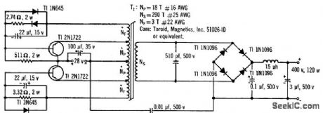
Circuit boosts 28 V d-c input to 400 V d-c with 85% efficiency, drawing 5 amp and operating at 10 kc.-120-Watt D-C/D-C Converter Operates From -55° to +125℃, Electronics, 36:2, p 15. (View)
View full Circuit Diagram | Comments | Reading(622)
20_watt_25_dB_16_to_30_MHz_SSB_linear_amplifiersupply_voltage_is_138_volts
Published:2009/7/21 5:53:00 Author:Jessie

20-watt 25 dB 1.6 to 30 MHz SSB linear amplifier.supply voltage is 13.8 volts (courtesy Motorola semiconductor Products Inc.). (View)
View full Circuit Diagram | Comments | Reading(687)
48_KV_OSCILLATOR_TYPE_CRT_SUPPLY
Published:2009/7/21 5:51:00 Author:Jessie
One of earliest circuits in which a-f sine-wave oscillator was used as power source. Filter capacitors are significantly smaller than in conventional line-transformer supplies.-NBS, Handbook Preferred Circuits Navy Aeronautical Electronic Equipment, Vol. 1, Electron Tube Circuits, 1963, p N14-2. (View)
View full Circuit Diagram | Comments | Reading(470)
Variable_speed_control_for_induction_motors
Published:2009/7/21 5:50:00 Author:Jessie
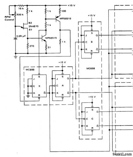
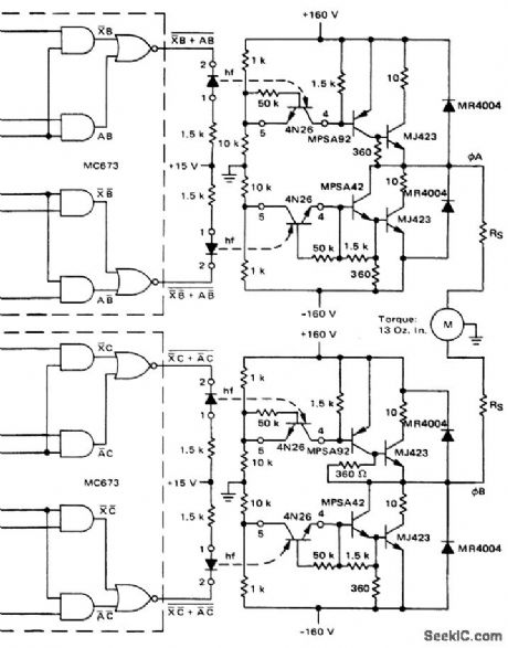

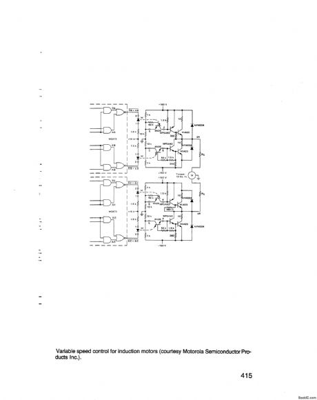
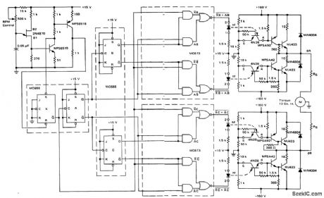
Variable speed control for induction motors (courtesy Motorola Semiconductor Pro-ducts Inc.). (View)
View full Circuit Diagram | Comments | Reading(784)
D_C_D_C_REGULATED_SUPPLY
Published:2009/7/21 5:50:00 Author:Jessie
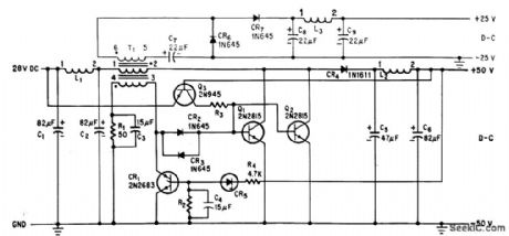
Efficiency is 93% in converting 28 V d-c to 25 and 50 V d-c for telemetry transmitter. Regulation is achieved by storing energy in magnetic field of coil during half of each switching cycle created by transistors Q1 and Q2 after Q3 initiates switching cycle. SCR CR1 and diode CR5 control percentage of time switching transistors are on.-N. Downs and B. van Sutphin, Solid-State Transmitter Ready for UHF Telemetry, Electronics, 37:17, p 76-80. (View)
View full Circuit Diagram | Comments | Reading(581)
VARIABLE_REMOTE_POWER_SUPPLY
Published:2009/7/21 5:48:00 Author:Jessie

Permits varying output d-c voltage of scr power supply without changing a-c input voltage. Conduction time of scr's during each half-cycle determines average power delivered to load. Conduction time is controlled with pulse gating circuit that is synchronized with a-c line and is phase-variable. Provides maximum output of 60 amp at 20 V.-B. F. Gilbreath, Variable High Current Remote Power Supply, EEE, 10:12, p 27-28. (View)
View full Circuit Diagram | Comments | Reading(1674)
High_low_AC_switch_for_light_dimming_or_small_motor_two_speed_control
Published:2009/7/21 5:46:00 Author:Jessie
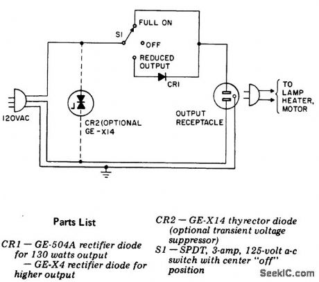
High-low AC switch for light dimming or small motor two-speed control (courtesy General Electric Company). (View)
View full Circuit Diagram | Comments | Reading(777)
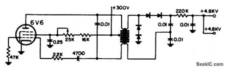
14_KV_AND_385_V_FOR_DARK_FACE_CRT
Published:2009/7/21 5:45:00 Author:Jessie
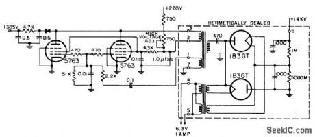
Uses two pentodes in parallel in a-f oscillator to provide sufficient power for final anode potential in oscillator-type supply.-NBS, Handbook Preferred Circuits Navy Aeronautical Electronic Equipment, Vol. 1, Electron Tube Circuits, 1963, p N14-3. (View)
View full Circuit Diagram | Comments | Reading(633)
Triac_full_wave_control_circuit_with_UJT_trigger_designed_for_a_900_watt_load
Published:2009/7/21 5:44:00 Author:Jessie
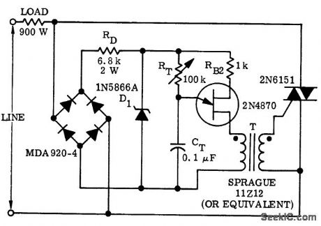
Triac full-wave control circuit with UJT trigger designed for a 900-watt load (courtesy Motorola Semiconductor Products Inc.). (View)
View full Circuit Diagram | Comments | Reading(1589)
CMOS_MARKER
Published:2009/7/21 5:30:00 Author:Jessie

Crystal-controlled marker generator uses any crystal from 100 kHz to 4 MHz. Requires only one CD4009 hex inverter and two CD4015 shift registers. Switches give choice of even. number division ratios up to 256. Used for locating band edges or subbands and for calibrating receivers. Transistor AM beeper is simple clamp that gates RF on or off, to facilitate location of marker in crowded bands.-K.W. Robbins, All Band Frequency Marker, 73 Magazine, June 1975, p 88-90. (View)
View full Circuit Diagram | Comments | Reading(2031)
TRIGGERED_THYRATRON_PULSER
Published:2009/7/21 5:02:00 Author:Jessie
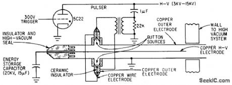
Coaxial rail gun generates high-velocity copper plasma when triggered by series-connected button guns energized through transformer by thyratron pulser. Vaporized copper from buttons shorts main 15-mfd capacitor, vaporizing inner copper high-voltage electrode. –M. F. Wolff,Plasma Engineering-Part 1: Generating and Heating Plasma, Electronics, 34:28, p 47-53. (View)
View full Circuit Diagram | Comments | Reading(2538)
RMS_Closed_loop_voltage_compensator
Published:2009/7/21 5:01:00 Author:Jessie
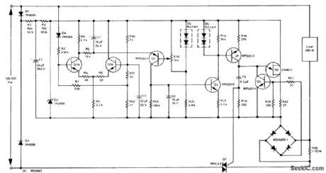
RMS Closed-loop voltage compensator (regulator).This circuit provides an output of 90 ±2volts RMS at 600 watts for aninput of 105 to 260 volts (courtesy Motorola Semiconductor Products Inc.). (View)
View full Circuit Diagram | Comments | Reading(707)
NAB_RECORD_PREAMPLIFIER
Published:2009/7/8 4:45:00 Author:May

View full Circuit Diagram | Comments | Reading(578)
Color_TV_358_MHz_crystal_oscillator_using_a_dual_gate_MOSFET_
Published:2009/7/21 5:28:00 Author:Jessie

Color TV 3.58 MHz crystal oscillator using a dual-gate MOSFET (courtesy Texas Instruments Incorporated). (View)
View full Circuit Diagram | Comments | Reading(3412)
Triac_relay_contact_protection_circuit
Published:2009/7/21 5:28:00 Author:Jessie
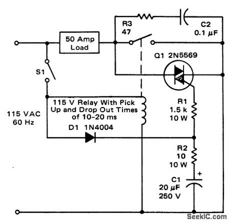
Triac relay-contact protection circuit (courtesy Motorola Semiconductor Products Inc.). (View)
View full Circuit Diagram | Comments | Reading(732)
70_80°C_THERMOMETER
Published:2009/7/8 4:44:00 Author:May
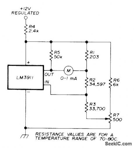
Uses National LM3911 IC having built-in temperature sensor.If no thermometer is available for calibration, set pot R7 to its midpoint. Article gives equations for calculating resistance values for other temperature and meter ranges. Applications indude monitoring of temperature in crystal oven. If permanenUy connected meter is not required, terminals can be provided for checking temperature with multimeter.-F. Schmidt, Precision Temperature Control for Crystal Ovens, Ham Radio, Feb. 1978, p 34-37. (View)
View full Circuit Diagram | Comments | Reading(514)
Direction_and_speed_control_for_series_wound_motors
Published:2009/7/21 5:27:00 Author:Jessie
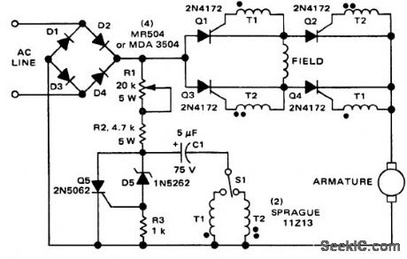
Direction and speed control for series-wound motors (courtesy Motorola Semiconductor Products Inc.). (View)
View full Circuit Diagram | Comments | Reading(1154)
TAPE_PLAYBACK_AMPLIFIER
Published:2009/7/8 4:44:00 Author:May

View full Circuit Diagram | Comments | Reading(564)
| Pages:957/2234 At 20941942943944945946947948949950951952953954955956957958959960Under 20 |
Circuit Categories
power supply circuit
Amplifier Circuit
Basic Circuit
LED and Light Circuit
Sensor Circuit
Signal Processing
Electrical Equipment Circuit
Control Circuit
Remote Control Circuit
A/D-D/A Converter Circuit
Audio Circuit
Measuring and Test Circuit
Communication Circuit
Computer-Related Circuit
555 Circuit
Automotive Circuit
Repairing Circuit