
Circuit Diagram
Index 946
Sawtooth_generator_with_negative_going_ramp_using_a_zener_and_a_PNPN_diode
Published:2009/7/20 22:06:00 Author:Jessie

Sawtooth generator with negative-going ramp using a zener and a PNPN diode (courtesy Motorola Semiconductor Products Inc.). (View)
View full Circuit Diagram | Comments | Reading(1067)
3_1_2_digit_multiplexed_MLC401_field_effect_LCD
Published:2009/7/20 21:52:00 Author:Jessie

3 1/2-digit multiplexed MLC401 field-effect LCD(courtesy Motorola Semiconductor Products Inc.). (View)
View full Circuit Diagram | Comments | Reading(741)
JFET_SAMPLE_AND_HOLD
Published:2009/7/20 21:51:00 Author:Jessie

Logic voltage is applied simultaneously to sample-and-hold JFETs. By matching input impedance and feed-back resistance and capacitance, errors due to ON resistance of JFETs are minimized.- FET Databook, National Semiconductor, Santa Clara, CA, 1977, p 6-26-6-36. (View)
View full Circuit Diagram | Comments | Reading(0)
6_V_at_20_A
Published:2009/7/20 21:50:00 Author:Jessie
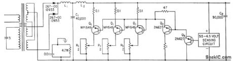
Constant-voltage ferrores-onant transformer with full-wave silicon rectifiers is supplemented by shunt transistors driven by error signal from zener-reference sensing circuit.-J. r. Keefe, Transformer and Shunt Transistors Regulate D-C Power Supply, Electronics, 34:20, p 99-101. (View)
View full Circuit Diagram | Comments | Reading(597)
Operational_amplifier_±15_volt_1_ampere_power_supply
Published:2009/7/20 21:50:00 Author:Jessie

Operational amplifier ±15-volt 1-ampere power supply. The ECG968 and ECG969 positive and negative regulators can be connected as shown to obtain a dual power supply. A clamp diode should be used at the output of the ECG968 to prevent latch-up problems. The regulators have thermal-overload and short-circuit protection. The input capacitors should be 0.33 μF if tantalum or Mylar, or 1.0μF if aluminum. Bypassing the output is also recommended. The same type of dual power supply can be constructed with other ratings of the ECG9XX series of regulator. Ratings are as follows: ECG960, +5 volts; ECG961, -5 volts; ECG962, +6 volts; ECG963,-6 volts; ECG966, +12 volts; ECG967,-12 volts; ECG968; +1 5volts, ECG969,-15 volts; and ECG972, +24 volts (courtesy GTE Sylvania Incorporated). (View)
View full Circuit Diagram | Comments | Reading(1700)
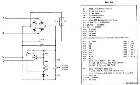
320_V_AT_60_MA
Published:2009/7/20 21:49:00 Author:Jessie
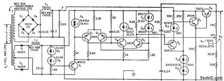
Silicon diodes in full-wave bridge feed seven-transistor regulator. Temperature-compensated silicon-junction zenet diode is basic reference element. Output is constant within 50 my, for use with digital-analog converter.-N. Aron, Precise Converter takes Current Analog of Digital voltage Pulses, Electronics, 35:32, p 68-71. (View)
View full Circuit Diagram | Comments | Reading(707)
80_watt_switching_regulator_supply_for_CATV_applications_with_24_volt_3_ampere_output
Published:2009/7/20 21:47:00 Author:Jessie
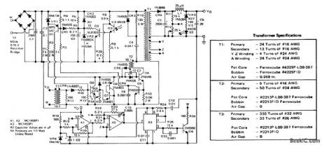
80-watt switching regulator supply for CATV applications with 24-volt 3-ampere output. This circuit operates above 18 kilohertz from a 40- to 60-volt 60-hertz square wave or from a DC standby source with input/output isolation (courtesy Motorola Semiconductor Products Inc.). (View)
View full Circuit Diagram | Comments | Reading(1127)
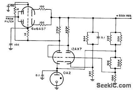
PENTODE_WITH_CONSTANT_REFERENCE_CURRENT
Published:2009/7/20 21:45:00 Author:Jessie

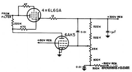
screen is fed directly from regulated voltage of shunt-regulating supply using VR-105 and VR-150 reference lubes to give -300 v.-NBS, Handbook Preferred Circuits Navy Aeronautical Electronic Equipment, Vol. 1, Electron Tube Circuits, 1963, p N2-2. (View)
View full Circuit Diagram | Comments | Reading(796)
35__50__60__75__100_watt_AF_power_amplifier
Published:2009/7/20 21:45:00 Author:Jessie


35-/50-/60-/75-/100-watt AF power amplifier (courtesy Motorola Semiconductor Products Inc.). (View)
View full Circuit Diagram | Comments | Reading(3125)
Line_operated_inverter_with_15_volt_DC_225_watt_output_
Published:2009/7/20 21:44:00 Author:Jessie
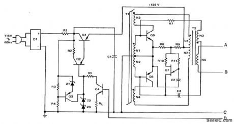
Line-operated inverter with 15-volt DC 225-watt output (courtesy Motorola Semiconductor Products Inc.). (View)
View full Circuit Diagram | Comments | Reading(828)
TWIN_TRIODE_CASCADE_1
Published:2009/7/20 21:43:00 Author:Jessie
Smaller load resistor improves frequency response. Both reference tube and comparison divider are loaded.-NBS, Handbook Preferred Circuits Navy Aeronautical Electronic Equipment, Vol. 1, Electron Tube Circuits, 1963, p N2-3. (View)
View full Circuit Diagram | Comments | Reading(852)
FAST_SAMPLE_AND_HOLD
Published:2009/7/20 21:42:00 Author:Jessie
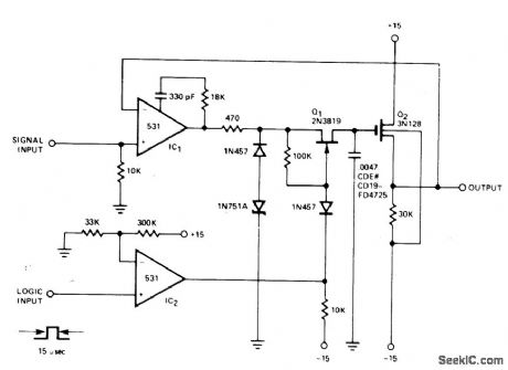
Strobe pulse developed from logic input of 531 opamp IC, turns on JFET Q1 to complete feedback loop to IC1, Q1, and Q2. C1 charges to voltage equal to that of input signal plus gate-to-source offset voltage of Q2. At end of strobe time, feedback loop is broken and C, holds voltage until time of next strobe pulse. Decay in output voltage between samplings is 1mV/s.- Signetics Analog Data Manual, Signetics, Sunnyvale, CA, 1977, p 643-644. (View)
View full Circuit Diagram | Comments | Reading(1016)
CURRENT_LIMITING_SUPPLY_WITH_REFERENCE_AMPLIFIER
Published:2009/7/20 21:41:00 Author:Jessie
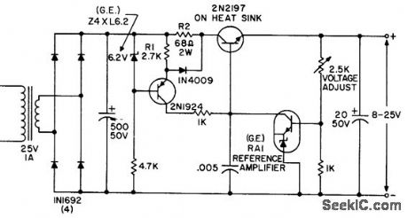
Variable 8 to 25-v supply limits output to 100 mc for protection against short-circuits. Regulation is 0.02% for line voltages from 105 to 130 v.- Transistor Manual, Seventh Edition, General Electric Co., 1964, p 232. (View)
View full Circuit Diagram | Comments | Reading(755)
105_MHz_gate_2_contralled_RF_amplifier_using_a_TIS152_dual_gate_MOSFET
Published:2009/7/20 22:34:00 Author:Jessie
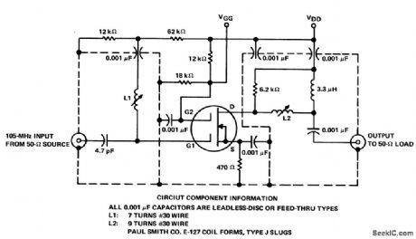
105 MHz gate-2-contralled RF amplifier using a TIS152 dual-gate MOSFET This circuit has been optimized for third-order intermodulation distortion(courtesy Texas Instruments Incorporated). (View)
View full Circuit Diagram | Comments | Reading(1419)
Real_time_5_digit_fluorescent_diode_display
Published:2009/7/20 22:33:00 Author:Jessie

Real-time 5-digit fluorescent diode display(courtesy Motorola Semiconductor Products Inc.). (View)
View full Circuit Diagram | Comments | Reading(829)
Voltage_controlled_ramp_generator_VCRG_using_a_PUT
Published:2009/7/20 22:31:00 Author:Jessie

Voltage-controlled ramp generator (VCRG) using a PUT. Setting the value of C to 0.0047 μF provides a change in frequency of 3.4 ms; setting it to 0.01 μF provides a change of 5.4 ms (courtesy Motorola Semiconductor Products Inc.). (View)
View full Circuit Diagram | Comments | Reading(882)
6_digit_fluorescent_triode_display
Published:2009/7/20 22:31:00 Author:Jessie

6-digit fluorescent triode display (courtesy Motorola Semiconductor Products Inc.). (View)
View full Circuit Diagram | Comments | Reading(494)
118_to_136_MHz_broadband_RF_amplifier_using_a_2N6083_bipolar_transistor
Published:2009/7/20 22:31:00 Author:Jessie
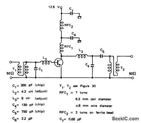
118 to 136 MHz broadband RF amplifier using a 2N6083 bipolar transistor. This circuit is ideal for mobile operation since the recommended supply voltage is 12.5 volts. It provides 30 watts output for a 4-watt input at 125 MHz (courtesy Motorola Semiconductor Products Inc.). (View)
View full Circuit Diagram | Comments | Reading(2449)
8_digit_fluorescent_triode_display
Published:2009/7/20 22:29:00 Author:Jessie

8-digit fluorescent triode display (courtesy Motorola Semiconductor Products Inc.). (View)
View full Circuit Diagram | Comments | Reading(1010)
Staircase_generator_1
Published:2009/7/20 22:28:00 Author:Jessie

Staircase generator. The number of steps is determined as follows: h = (11RLVBR)/[(Vp - VBR)tp], where n is the number of steps, VBR is the break-down voltage of the PNPN diode, VP is the peak pulse with and tp is the pulse width (courtesy Motorola Semiconductor Products Inc.). (View)
View full Circuit Diagram | Comments | Reading(964)
| Pages:946/2234 At 20941942943944945946947948949950951952953954955956957958959960Under 20 |
Circuit Categories
power supply circuit
Amplifier Circuit
Basic Circuit
LED and Light Circuit
Sensor Circuit
Signal Processing
Electrical Equipment Circuit
Control Circuit
Remote Control Circuit
A/D-D/A Converter Circuit
Audio Circuit
Measuring and Test Circuit
Communication Circuit
Computer-Related Circuit
555 Circuit
Automotive Circuit
Repairing Circuit