
Circuit Diagram
Index 952
Power_generation_circuit_using_n_number_of_AD7524_8_bit_D_A_conveners
Published:2009/7/21 4:34:00 Author:Jessie
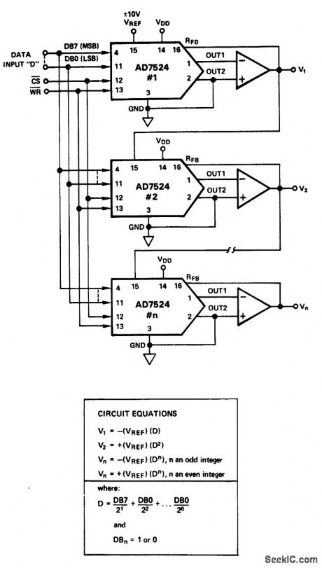
Power generation circuit using n number of AD7524 8-bit D/A conveners (courtesy Analog Devices, Inc.). (View)
View full Circuit Diagram | Comments | Reading(730)
CAMERA_CONTROL
Published:2009/7/21 4:33:00 Author:Jessie
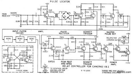
Circuit separates 3.5-kc pulses from other subcarrier signals at input filter, then amplifies, rectifies pulses, and squares pulses at Schmitt trigger. Four cameras can be controlled by system from single 460-Mc radio link.-F. M. Gardner and L. R. Hawn, Camera Control System for Rocket Sled Tests, Electronics, 33:14, p 63-65. (View)
View full Circuit Diagram | Comments | Reading(734)
Divider_circuit_using_an_AD533_multiplier_divider_chip
Published:2009/7/21 4:28:00 Author:Jessie
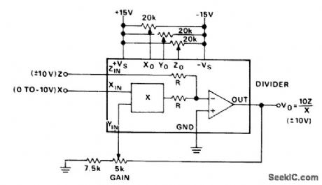
Divider circuit using an AD533 multiplier/divider chip. Set all pots at midrange. With Z equal to zero volts, trim Zo to hold the output constant as X is varied from -10 volts DO to - 1 volt DC. With Z equal to zero volts and X equal to - 10 volts DC trim Yo for zero volts DC. With Z equal to X or -X trim Xo for the minimum worst-case variations as X is varied from -10 volts DC to -1 volt DC. With Z equal to X or-X trim the gain for the closest average approach to ±10volts DC output as X is varied from -10 volts DC to -3 volts DC (courtesy Analog Devices, Inc.). (View)
View full Circuit Diagram | Comments | Reading(875)
Color_TV_video_IF_system
Published:2009/7/21 4:28:00 Author:Jessie
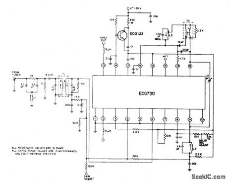
Color TV video IF system. Gain is typically 75 dB at 45 MHz tor the IF amplifier and 12 dB for the video amplifier. The chip contains a zener reference diode for convenient and economical power supply regulation (courtesy GTE Sylvania Incorporated). (View)
View full Circuit Diagram | Comments | Reading(737)
Video_signal_processor_for_eith_B﹠W_or_color_TV
Published:2009/7/21 4:24:00 Author:Jessie
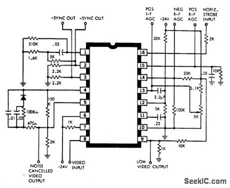
Video signal processor for eith B﹠W or color TV The chip contains a keyed AGC amplifier that provides forward AGC voltage for video IF amplifiers and tuners equipped with NPN bipolar transistors. It provides compdsite sync outputs with positive and negative going signals. There's also reverse AGC voltage for tuners equipped with MOSFETs, PNP bipolar transistors, or tubes in the BF stage. The video output is a low-impedance emitter follower. In addition there's a preset noise detector for gating the chip's sync separator and AGC detector (courtesy GTE Sylvania Incorporated). (View)
View full Circuit Diagram | Comments | Reading(955)
PRINT_TIMER
Published:2009/7/21 4:24:00 Author:Jessie

Uses radar phantastron circuit to give correct combination of exposure time and color filtier for desired contrast and density. R1 sets exposure time from 6 to 60 seconds and R2 regulates contrast.-J. D. Weir, Print Timer Controls Density and Contrast, Electronics, 31:7, p 108-109. (View)
View full Circuit Diagram | Comments | Reading(824)
Very_high_impedance_instrumentation_amplifier_using_two_AD510s_and_two_AD515s
Published:2009/7/21 3:12:00 Author:Jessie

Very-high impedance instrumentation amplifier using two AD510s and two AD515s (courtesy Analog Devices, Inc.). (View)
View full Circuit Diagram | Comments | Reading(691)
Commutator_network_using_N_channel_MOSFETs
Published:2009/7/21 3:11:00 Author:Jessie

Commutator network using N-channel MOSFETs. All semiconductors are 2N4351s. Each switch has a three-input AND gate in series with the gate drive (courtesy Motorola Semiconductor Products Inc.). (View)
View full Circuit Diagram | Comments | Reading(782)
Precision_high_CMV
Published:2009/7/21 3:09:00 Author:Jessie

Precision high CMV (common mode voltage) analog isolator. This circuit provides up to 1500 volts DC CMV isolation (courtesy Analog Devices, Inc.). (View)
View full Circuit Diagram | Comments | Reading(633)
Four_quadrant_multiplication_with_the__in_bipolar_operation
Published:2009/7/21 3:09:00 Author:Jessie

Four-quadrant multiplication with the AD7520 in bipolar operation. The Intersil AD7520 is an 18-pin multiplying D/A converter. A logic one input at any digital input forces the corresponding ladder switch to steer the bit current to the IOUT1 bus. A logic zero input forces the bit current to the IOUT2 bus. For any code the IOUT1 and IOUT2 bus currents are complements of one another. The current amplifier at IOUT2 changes the polarity of IOUT2 current and the transconductance amplifier at lour output sums the two currents. This configuration doubles the output range but halves the resolution of the D/A convener. For the offset adjustment set VREF to approximately +10 volts and connect all digital inputs to logic one. Adjust the IOUT2 amplifier offset zero pot for 0V ±1 mV at IOUT2 amplifier output. Connect the MSB to logic one and all other bits to logic zero. Adjust IOUT1 offset zero pot for 0V ±mV at VOUT. For the gain adjustment connect all digital inputs, to VDD. Monitor VOUT for a -VREF (1- 2- (n - 1)) volt reading, where n is equal to 10. To increase VOUT connect a series resistor, 0 to 500 ohms, in the lour amplifier feedback loop. To decrease VOUT connect a series resistor, 0 to 500 ohms, between the reference voltage and pin 15 (courtesy Intersil, Inc.). (View)
View full Circuit Diagram | Comments | Reading(1101)
Fixed_divide_by_ten_prescaler_using_an_MC1034,_MC1032,_MC1013_andMC1018
Published:2009/7/21 3:08:00 Author:Jessie

Fixed divide-by-ten prescaler using an MC1034, MC1032, MC1013 and MC1018(courtesy Motorola Semiconductor Products inc.). (View)
View full Circuit Diagram | Comments | Reading(629)
SQUARE_WAVE_GENERATOR
Published:2009/7/21 3:06:00 Author:Jessie

A square wave for driving a stepper motor driver can be obtained from this circuit, which uses a CMOS timer in an oscillator circuit. A potentiometer can be used to obtain variable-frequency output. (View)
View full Circuit Diagram | Comments | Reading(0)
45_MHz_color_TV_sound_IF_amplifier_using_ECG703A
Published:2009/7/21 3:49:00 Author:Jessie

4.5 MHz color TV sound IF amplifier using ECG703A. In a color TV the 4.5 MHz IF is not generated in the video detector as in B&W sets. A separate transistor sound detector, driven from thefinal video IF amplifier, is used to develop the 4.5 MHz IF. The drivertransformer at the input of the chip is tuned to 4.5 MHz. The output drives a conventional ratio detector, which provides good AM rejection well belowfull limiting (courtesy GTE Sylvania Incorporated).
(View)
View full Circuit Diagram | Comments | Reading(1520)
Variable_gain_amplifier
Published:2009/7/21 3:48:00 Author:Jessie

Variable gain amplifier (two-quadrant divider). Examples of gains at various codes are given in the table (courtesy Analog Devices, Inc.). (View)
View full Circuit Diagram | Comments | Reading(0)
Complete_RGB_video_output_stage_for_color_TV_using_the_ECG713_chip
Published:2009/7/21 3:45:00 Author:Jessie

Complete RGB video output stage for color TV using the ECG713 chip (courtesy GTE Sylvania Incorporated). (View)
View full Circuit Diagram | Comments | Reading(627)
Vector_computation_circuit_for_n_variables_using_three_434_multiplier_dividers_and_two_AD741_op_amps
Published:2009/7/21 3:43:00 Author:Jessie

Vector computation circuit for n variables using three 434 multiplier/dividers and two AD741 op amps (courtesy Analog Devices, Inc.). (View)
View full Circuit Diagram | Comments | Reading(824)
Vector_computation_circuit_for_VC2_=_VA2___VB2_using_the_433_multiplier_divider_and_two_AD741_op_amps
Published:2009/7/21 3:42:00 Author:Jessie

Vector computation circuit for VC2 = VA2 + VB2 using the 433 multiplier/divider and two AD741 op amps (courtesy Analog Devices, Inc.). (View)
View full Circuit Diagram | Comments | Reading(644)
DIODE_SWITCHED_IF_FILTER
Published:2009/7/8 5:06:00 Author:May

Used in 1.8-2 MHz communication receiver having wide dynamic range 1N914 diodes select collins mechanical filter F455FD-04 FL3 (400-Hz bandwidth) or F455FD-25 FL4(2.5-kHz bandw)Reverse biasis applied to nonconducting diodes to lesson leakage through switching diodes Filteris located between IF preamρ and main IF strip of receiver Two-part article gives all other circuits of receiver,-D.DeMaw,His Eminence-the Receiver,QST,Part 1-June 1976,p 27-30(Part2-July 1976,p 14-17). (View)
View full Circuit Diagram | Comments | Reading(857)
358_MHz_injection_locked_oscillator_for_color_TVUsing_one_ECG703A_IC
Published:2009/7/21 3:41:00 Author:Jessie

3.58 MHz injection-locked oscillator for color TV,Using one ECG703A IC. The burst transformer induces the chroma reference directly intothefeedback loop of the oscillator, thereby locking the oscillator in phase with the transmitted burst (courtesy GTE Sylvania Incorporated). (View)
View full Circuit Diagram | Comments | Reading(1061)
ZERO_SUPPRESSION
Published:2009/7/8 5:06:00 Author:May

Opamp is used in in, verting configuration at output of temperature-sensing bridge, so noninverting input of opamp can be used for suppressing meter zero when temperature range for application is 29 to 42°C .Calibration control is set for gain of about 17.2 to make meter direct-reading. Article gives operation details and methods of improving temperature stability of circuit.-R. J. Isaacs, Optimizing Op-Amps, Wireless World, April1973, p 185-186. (View)
View full Circuit Diagram | Comments | Reading(0)
| Pages:952/2234 At 20941942943944945946947948949950951952953954955956957958959960Under 20 |
Circuit Categories
power supply circuit
Amplifier Circuit
Basic Circuit
LED and Light Circuit
Sensor Circuit
Signal Processing
Electrical Equipment Circuit
Control Circuit
Remote Control Circuit
A/D-D/A Converter Circuit
Audio Circuit
Measuring and Test Circuit
Communication Circuit
Computer-Related Circuit
555 Circuit
Automotive Circuit
Repairing Circuit