Electrical Equipment Circuit
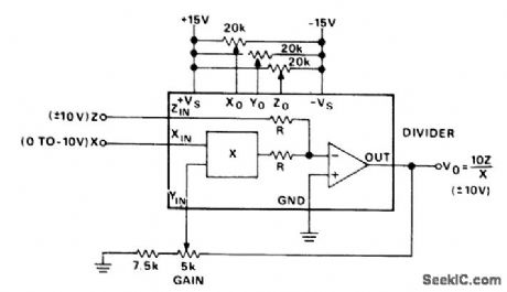
Divider_circuit_using_an_AD533_multiplier_divider_chip
Published:2009/7/21 4:28:00 Author:Jessie | From:SeekIC

Divider circuit using an AD533 multiplier/divider chip. Set all pots at midrange. With Z equal to zero volts, trim Zo to hold the output constant as X is varied from -10 volts DO to - 1 volt DC. With Z equal to zero volts and X equal to - 10 volts DC trim Yo for zero volts DC. With Z equal to X or -X trim Xo for the minimum worst-case variations as X is varied from -10 volts DC to -1 volt DC. With Z equal to X or-X trim the gain for the closest average approach to ±10volts DC output as X is varied from -10 volts DC to -3 volts DC (courtesy Analog Devices, Inc.).
Reprinted Url Of This Article:
http://www.seekic.com/circuit_diagram/Electrical_Equipment_Circuit/Divider_circuit_using_an_AD533_multiplier_divider_chip.html
Print this Page | Comments | Reading(3)

Article Categories
power supply circuit
Amplifier Circuit
Basic Circuit
LED and Light Circuit
Sensor Circuit
Signal Processing
Electrical Equipment Circuit
Control Circuit
Remote Control Circuit
A/D-D/A Converter Circuit
Audio Circuit
Measuring and Test Circuit
Communication Circuit
Computer-Related Circuit
555 Circuit
Automotive Circuit
Repairing Circuit
Code: