
Circuit Diagram
Index 949
Gated_oscillator_using_an_MC1545G_video_amplifier_chip
Published:2009/7/20 23:19:00 Author:Jessie

Gated oscillator using an MC1545G video amplifier chip (courtesy Motorola Semiconductor Products Inc.). (View)
View full Circuit Diagram | Comments | Reading(468)
SINE_COSINE_OSCILLATOR
Published:2009/7/21 1:44:00 Author:Jessie

Two oscillators in cascade with positive feedback generate two sine waves in quadrature (differing in phase by 90°). Limiting network D1-D2-R5 is used around A2 to prevent oscillator from stabilizing at saturation limit of A2. R5 is used to set output at any level above zener limits of D1-D2. Frequency is 1 kHz for values shown.-W. G. Jung, IC Op-Amp Cookbook, Howard W. Sams, Indianapolis, IN, 1974, p 371-372. (View)
View full Circuit Diagram | Comments | Reading(868)
Mltiplier_with_op_amp_level_shift
Published:2009/7/21 1:44:00 Author:Jessie
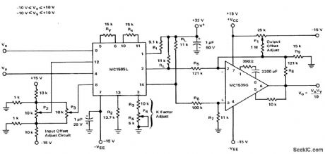
Mltiplier with op amp level shift (courtesy Motorola Semiconductor Products Inc.). (View)
View full Circuit Diagram | Comments | Reading(761)
BAND_EDGE_MARKER
Published:2009/7/21 1:41:00 Author:Jessie

Series-tuned Colpitts crystal oscillator feeding 10-inch insulated-wire antenna provides sufficient signal radiation for pickup by nearby communication receiver. Used to provide band-edge marker for calibrating receiver tuning dial so receiver meets FCC rules for checking transmitter frequency when using VFO rather than crystal control for Novice transmitter in amateur bands. Crystal can be either for 40- or 80-meter band. Although band-edge frequency is convenient for warning when transmitter is going off frequency, calibration can be done with any frequency in or near band of interest. C5 is 0.25 μF.-K. Negoro, A Band-Edge Marker Generator, QST, April 1973, p 16-17. (View)
View full Circuit Diagram | Comments | Reading(817)
LAB_GENERATOR_CALIBRATOR
Published:2009/7/21 1:39:00 Author:Jessie

Portable design operating from single flashlight D cell uses National LM3909 flasher IC to produce clean rectangular wave that can be adjusted to exactly 1 V. Pulse width is 1.5 ms and OFF interval between pulses is 5.5 ms. Useful for calibrating oscilloscopes and adjusting their probes. Article describes operation of circuit in detail, Current drain is low enough to give 500 h of operation.-P. Lefferts, Power-Miser Flasher IC Has Many Novel Applications, EDN Magazine, March 20, 1976, p 59-66. (View)
View full Circuit Diagram | Comments | Reading(542)
UNIVERSAL_TEST_OSCILLATOR
Published:2009/7/21 1:38:00 Author:Jessie

Crystal is in feedback path of Pierce oscillator, between base and collector of al, with 2.5-mH RF choke in place of tuned collector circuit. Oscillator works from 400 kHz to 20 MHz, depending on crystal. Designed for fundamental crystals; third overtone types will oscillate but at fun-damental. Value of 01 is for 1 MHz and higher; increase to 330 pF for lower frequencies. An-tenna can be 20-inch wire; increasing length increases signal radiation. Can be used as signal source for receiver alignment (with either radiated or probe-coupled signal), as marker generator, or in combination with station receiver as code-practice oscillator.-D. DeMaw, Build a UTO-1, QST, Oct. 1977, p 19-21. (View)
View full Circuit Diagram | Comments | Reading(2273)
455_kHz_FOR_IF_ALIGNMENT
Published:2009/7/21 1:37:00 Author:Jessie

Simple crystal-controlled signal generator serves for aHgning IF strips. Amplitude modulator uses Colpitts 1-kHz oscillator circuit, with surplus 88-mH toroid in tank circuit; tie two adjacent leads together to provide center tap. T1 is 455-kHz IF transformer from AM transistor radio, used to tune drain circuit and obtain low output impedance. Current drain is about 7 mA with 12-V supply and 5 mA with 9-V battery.-C. Hall, 455-kHz 1-F Alignment Signal Generator, Ham Radio, Feb. 1974, p 50-52. (View)
View full Circuit Diagram | Comments | Reading(3131)
Arc_tangent_function_from_the_4301_multifunction_chip
Published:2009/7/21 1:37:00 Author:Jessie
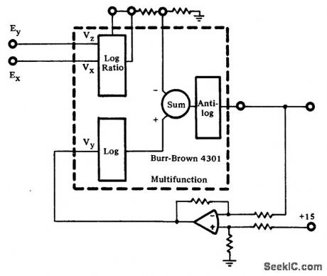
Arc tangent function from the 4301 multifunction chip (courtesy Burr-Brown Research Corporation). (View)
View full Circuit Diagram | Comments | Reading(642)
Sine_function_from_the_4301_multifunction_chip
Published:2009/7/21 1:36:00 Author:Jessie
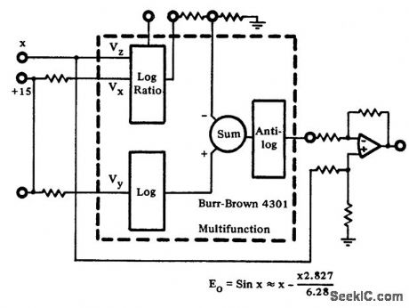
Sine function from the 4301 multifunction chip (courtesy Burr-Brown Research Corporation). (View)
View full Circuit Diagram | Comments | Reading(675)
25_kHz_CALIBRATOR
Published:2009/7/21 1:36:00 Author:Jessie

Addition of one 7473 dual JK flip-flop IC to circuit of Radio Shack 28-140 100-kHz calibrator kit provides conversion to 25 kHz for checking frequency settings of am-ateur receivers. Amplitude of output is 5 V P-P square wave with rich harmonic content. Originally designed for use with HW-8 Heathkit am ateur receiver. Output of calibrator is coupled to receive side of antenna relay through 10-pF capacitor. Article covers initial calibration.-D. Karpiej, A 25-kHz Calibrator for the HW-8, QST, Oct. 1978, p 20-21. (View)
View full Circuit Diagram | Comments | Reading(1631)
Square_rooter_circuit_using_the_435_multiplier_divider_chip
Published:2009/7/21 1:35:00 Author:Jessie
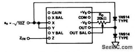
Square rooter circuit using the 435 multiplier/divider chip (courtesy Analog Devices, Inc.). (View)
View full Circuit Diagram | Comments | Reading(608)
Divider_circuit_with_digitally_controlled_gain
Published:2009/7/21 1:34:00 Author:Jessie
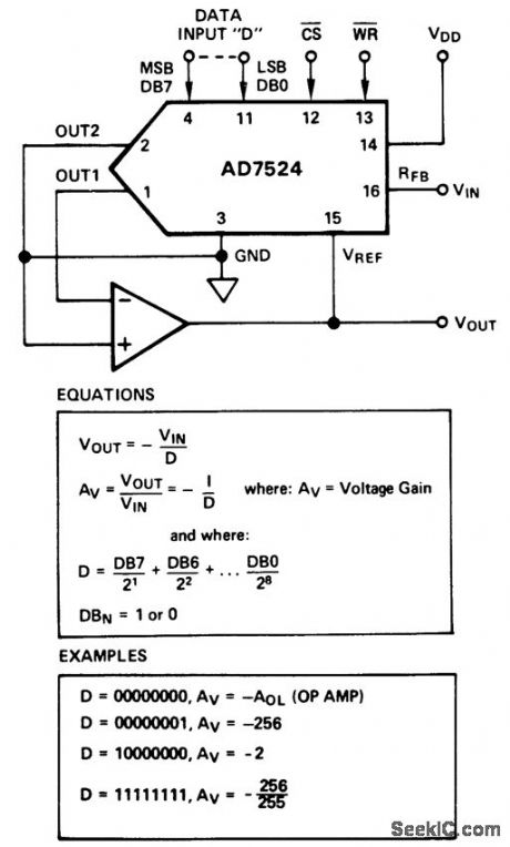
Divider circuit with digitally controlled gain (courtesy Analog Devices, Inc.). (View)
View full Circuit Diagram | Comments | Reading(659)
TRACKING_GENERATOR
Published:2009/7/21 1:34:00 Author:Jessie

Used with spectrum analyzer to generate CW signal corresponding to frequency to which analyzer is tuned, for evaluation of filter response.Q1 and Q2 provide gain and isolation between 200-MHz oscillator, Q3 and first IF amplifier of analyzer. R1 provides fine tuning. MX1 mixes 200-MHz output with signal from 200-300 MHz first local oscillator to provide 100-kHz to 100-MHz tracking signal. Optional 130-MHz low-pass filter attenuates 400-500 MHz component generated by mixer in tracking generator-W, Ryder, Spectrum Analyzer Tracking Generator, Ham Radio, April 1978, p 30-32. (View)
View full Circuit Diagram | Comments | Reading(1339)
SERIES_DIODE_MAGNETRON_MODULATOR
Published:2009/7/21 0:08:00 Author:Jessie

In variation of spark-gap modulator, 25 pnpn diodes in series with pulse-forming networks (PFN) are switched by trigger and resulting voltage transient to supply 8,700 v at 35 amp to load. Success depends on availability of 700-v diodes.-F. A. Gateka and M. L. Embree, Semiconductor Modulators for Modern Magnetrons, Electronics, 35:37, p 42-45. (View)
View full Circuit Diagram | Comments | Reading(630)
PULSE_TIME_MODULATOR_USES_TWO_QUAD_RANT_MULTIPLIER
Published:2009/7/21 0:07:00 Author:Jessie

Output transistor Q3 servas as series switch driven by Q2 and magnetic modulator to give accurate analog multiplication.-W. R. Seegmiller, Accurate Analog Computation with Pulse-Time Modulation, Electronic, 35:13, p 54-57. (View)
View full Circuit Diagram | Comments | Reading(604)
CHOPPER_MODULATOR
Published:2009/7/21 0:06:00 Author:Jessie

Reduces output signal null level by balancing out zero input signal. Null levels con be maintained in microvolt region by proper shielding. Long time drift stability is less than 1 my referred to output. Used with strain gage and other low-level transducer signals.-L. S. Klivans, Modulators for Automatic Control Systems, Electronics, 31:1, p 82-84. (View)
View full Circuit Diagram | Comments | Reading(756)
BALANCED_TRIODE_SINE_WAVE_MODULATOR
Published:2009/7/21 0:04:00 Author:Jessie


Gives sinusoidal output without filtering-Can be used for either open-loop or error signal modulation when high input impedance and low-distortion sinusoidal output are required. Long-term drift stability is less than 1 mv per hour referred to output.-L. S. Klivans, Modulators for Automatic Control Systems, Electronics, 31:1, p 82-84. (View)
View full Circuit Diagram | Comments | Reading(559)
LINEAR_PWM_FOR_05_TO_175_V
Published:2009/7/21 0:03:00 Author:Jessie

Tubes V4 and V5 form bistable mvbr that will accept modulation voltage range of 350:1 from 0.5v to175 v, at point A. V3 is Miller ntegrator.Wilh 0.055 mfd for C1, pulse lengths are 61 and 173 millisec for limits of modulation voltage. Linearity is nearly perfect.-J,E,Frecker, A Pulse Width modulator, EEE, 10:12,p 28-300 (View)
View full Circuit Diagram | Comments | Reading(445)
2_KV_MODULE_OF_MAGNETRON_MODULATOR
Published:2009/7/21 0:02:00 Author:Jessie

With terminal 6 at +2,000 v, voltage-regulator diodes maintain 400 v across each pnpn transistor. Lowest transistor receives 0.5.amp, 3-v trigger at its gate.-F. A. Gateka and M. L. Embree, Semiconductor Modulators for Modern Magnetrons, Electronics, 35:37, p 42-45. (View)
View full Circuit Diagram | Comments | Reading(733)
HYBRID_DIODE_TUBE_PULSE_MODULATOR
Published:2009/7/21 0:01:00 Author:Jessie

Closely spaced pulses of any length, with 15-nsec rise and fall times al 550 V and 1.4 amp are produced for modulating traveling-wave tube by combining fast response of four-layer diodes with current-handling capabilities of tubes.-E. H. Heckman, Three New Approaches to Pulse Modulation, Electronics, 36:18, p 62-64. (View)
View full Circuit Diagram | Comments | Reading(541)
| Pages:949/2234 At 20941942943944945946947948949950951952953954955956957958959960Under 20 |
Circuit Categories
power supply circuit
Amplifier Circuit
Basic Circuit
LED and Light Circuit
Sensor Circuit
Signal Processing
Electrical Equipment Circuit
Control Circuit
Remote Control Circuit
A/D-D/A Converter Circuit
Audio Circuit
Measuring and Test Circuit
Communication Circuit
Computer-Related Circuit
555 Circuit
Automotive Circuit
Repairing Circuit