
Circuit Diagram
Index 954
SWITCHED_MODE_MOTOR_SPEED_CONTROLLER
Published:2009/7/8 4:59:00 Author:May
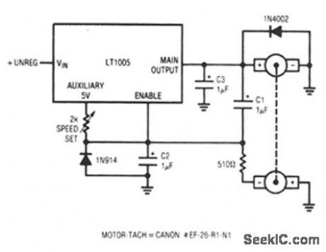
This circuit uses a tachometer to generate a feedback signal which is compared to a reference supplied by the auxiliary output. When power is applied, the tachometer output is zero and the regulator output comes on, forcing current into the motor. As motor rotation increases, the negative tachometer output pulls the enable pin toward ground. When the enable pin's threshold voltage is reached, the regulator output decreases and the motor slows. C1 provides positive feedback, ensuring clean transitions. In this fashion, the motor's speed is servo-controlled at a point determined by the 2-KΩ) potentiometer setting. The regulator free-runs at whatever frequency and duty cycle are required to maintain the enable pin at its threshold.The loop bandwidth and stability are set by C2 and C3. The 1N914 diode prevents the negative output tachometer from pulling the enable pin below ground, and the 1N4002 commutates the motor's negative flyback pulse. (View)
View full Circuit Diagram | Comments | Reading(731)
DUAL_POLARITY_VARIABLE_D_C_SUPPLY
Published:2009/7/21 5:55:00 Author:Jessie
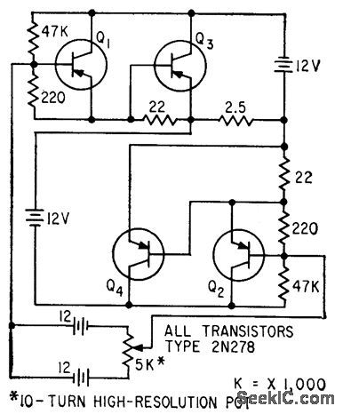
Diagonally symmetrical power transistor circuit permits smooth load current variation over range of several amperes at either polarity. Rectifier supply can be used in place of storage batteries. Maximum current drain from two 12-V dry cells in 5K potentiometer control circuit is 7 ma.-R. R.Bockemuehl, Transistor Rectifier Gives D-C of Either Polarity, Electronics, 32:25, p 76. (View)
View full Circuit Diagram | Comments | Reading(639)
Complete_TV_sound_system_that_provides_approximately_2_watts_ofaudio_power
Published:2009/7/21 4:51:00 Author:Jessie

Complete TV sound system that provides approximately 2 watts ofaudio power.Sound detection is accomplished through a coincidence discriminatorin thechipthat requlres only one RLC phase shift network,supply for the chip should be approximately 16 volts,Selectthe value of resistor R toobtain 11.6 volts at pin 14 ofthe ECG748(courtesy GTE Sylvania Incorporated). (View)
View full Circuit Diagram | Comments | Reading(685)
Color_TV_chroma_demodulator_with_RGB_output_matrix
Published:2009/7/21 4:49:00 Author:Jessie

Color TV chroma demodulator with RGB output matrix. By applying a positive going blanking pulse to pin 6, blanking ofthe picture cluing line and frameflyback is achieved (courtesy GTE Sylvania Incorporated). (View)
View full Circuit Diagram | Comments | Reading(1157)
Remote_control_for_lamp_or_appliance_using_a_filament_transformer
Published:2009/7/21 4:49:00 Author:Jessie
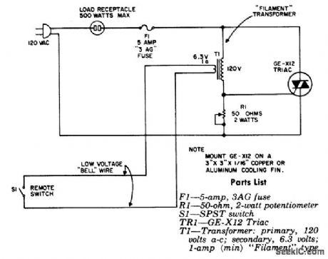
Remote control for lamp or appliance using a filament transformer. The circuit can handle up to 500 watts. R1 is adjusted for the highest resistance that will not trigger the triac with S1 open (courtesy General Electric Company). (View)
View full Circuit Diagram | Comments | Reading(585)
TV_TRANSMITTER
Published:2009/7/8 4:58:00 Author:May

This transmitter is capable of two levels of rf power. For low-power wireless video, like in a house or office, where simultaneous monitoring of program material is desirable without cumbersome hookups, 1-30 mW is available. For longer ranges up to several miles, as in amateur (ham) TV, security, and surveillance purposes, 2 W into a 50-Ω oad is available. (View)
View full Circuit Diagram | Comments | Reading(88)
SERVO_SYSTEM_CONTROLLER
Published:2009/7/8 4:57:00 Author:May
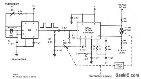
To control a servo motor remotely, the 555 needs only six extra components. (View)
View full Circuit Diagram | Comments | Reading(2782)
EFFICIENT_SWITCHING_CONTROLLER
Published:2009/7/8 4:56:00 Author:May

This high-performance switching controller for a low-power dc servo motor uses a symmetrical complementary-transistor bridge. The bridge acts as a reversing switch between the motor and a single-ended power supply. Since the transistors operate either fully on or completely off, except during a very short transition period, much less heat is dissipated than in linear-amplifier circuits. Damping is provided by the circuit's inherent dynamic braking. Since either maximum or zero voltage is applied to the motor, the dynamic response is faster than that of linear servo drives. (View)
View full Circuit Diagram | Comments | Reading(2500)
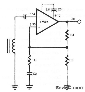
FLAT_RESPONSE_TAPE_AMPLIFIER
Published:2009/7/8 4:50:00 Author:May
View full Circuit Diagram | Comments | Reading(611)
_125_to__200℃_WITH_1°_ACCURACY
Published:2009/7/8 4:50:00 Author:May
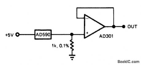
Use of factory-trimmed AD590 IC temperature sensor gives wide temperature range with minimum number of parts. Other temperature scales can be obtained by offsetting AD301 buffer opamp.-J. Williams, Designer's Guide to: Temperature Measurement, EDN Magazine, May 20, 1977, p 71-77. (View)
View full Circuit Diagram | Comments | Reading(987)
MAGNETIC_PHONO_PREAMPLIFIER
Published:2009/7/8 4:49:00 Author:May

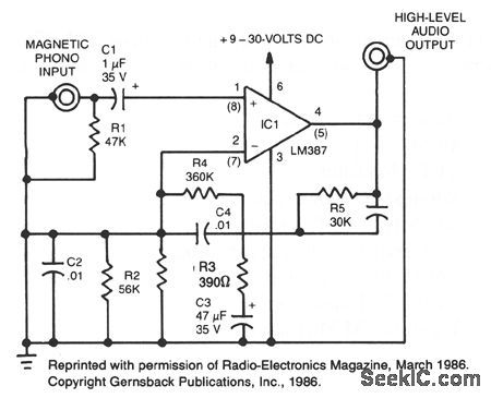
This simple stereo amplifier uses a National LM387IC. The piN numbers in parentheses are for one channel, and those not in parentheses are for the other channel. The supply voltage can be + 9 to + 30 Vdc at about 10 mA. The output voltage swing is about VCC-2 V pk-pk. The preamp should be able to deliver at least 5 V. (View)
View full Circuit Diagram | Comments | Reading(0)
TRANSISTOR_SENSOR
Published:2009/7/8 4:48:00 Author:May
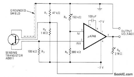
Use of bipolar supply for opamp makes electronic thermometer circuit fully linear even at low temperatures. Accuracy is within 0.05°C. Zero point is set by R4 and gain by R6—C .J .Koch,Diode or Transistor Makes Fully Linear Thermomete,Electronics,May 13,1976,p 110-112. (View)
View full Circuit Diagram | Comments | Reading(2373)
PWM_SPEED_CONTROLAND_ENERGY_RECOVERING_BRAKE
Published:2009/7/8 4:48:00 Author:May
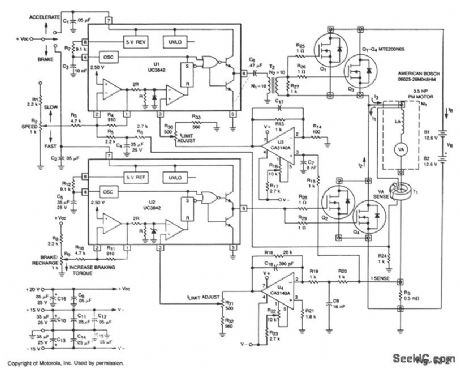
This circuit uses the main drive motor as a generator/brake to recover the battery charge during vehicle braking. When this is done, it can increase the overall range and efficiency of an electric vehicle.
In the accelerate mode, Q1 through Q3 receive gate pulses from U1, an on-line, current-mode, PWM controller IC. Assuming negligible effects of R, when Q1 through Q3 turn on, current I1 builds up through the motor at a rate of:
d/I1=VB-VA
where: VA = Battery voltage VB= Motor's back EMF LA = Motor inductance in henries
Motor current and torque continue to rise until the voltage on the ISENSE line is greater than IRESET, as determined by the speed potentiometer. At this time, Q1 through Q3 are switched off, current I2 begins to flow and decreases at a rate of: dI2 VA — = — dt LA
until the next clock period begins.As vehicle braking occurs, accelerate PWM IC U1 is switched off and braking PWM IC U2 and Q2 through Q4 are switched on. During this time, the back EMF source voltage causes current I3 to begin to flow at the rate of:
dI3 VA — = — dt LA
The current I3 continues to rise until ISENSE is greater than IRESET. Now, Q2 through Q4 are switched off and IB is forced to flow back into the storage battery, thus energy is recovered.
The braking torque produced by the motor is proportional to the average reverse current that flows through the motor on the duty cycle of Q2 through Q4. The braking force can continue until: VA =0
For reliable performance, voltage supplies should be independent of the main battery voltage.
(View)
View full Circuit Diagram | Comments | Reading(1295)
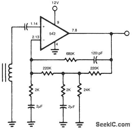
TWO_POLE_NAB_TYPE_PREAMP
Published:2009/7/8 4:46:00 Author:May

View full Circuit Diagram | Comments | Reading(589)
Divider_circuit_using_the_435_multiplier_divider_chip
Published:2009/7/21 3:32:00 Author:Jessie

Divider circuit using the 435 multiplier/divider chip (courtesy Analog Devices, Inc.). (View)
View full Circuit Diagram | Comments | Reading(639)
Divider_circuit_using_the_433_multiplier_divider_chip
Published:2009/7/21 3:31:00 Author:Jessie

Divider circuit using the 433 multiplier/divider chip (courtesy Analog Devices, Inc.). (View)
View full Circuit Diagram | Comments | Reading(642)
6O0_kHz_TO_12_MHz
Published:2009/7/21 3:23:00 Author:Jessie


Uses Motorola MC4024P or HEP3805P dual voltage-controlled MVBR or VCO. 0ne half is used to produce rectangular RF output and other half to generate rectangular 1-kHz modulation frequency. RF output frequency is proportional to 11C, with 365-pF variable capacitor providing tuning over 20:1 range from 600 kHz to 12 MHz. Use large dial for calibration. Half of MC3029P line-driver NAND gate follows each of MVBRs in MC4024P to provide isolation and to drive 50-Ohm lines with either output. Output voltage is well over 1 V P-P. T1 is 88-mH toroid with 30 turns No. 26 enamel wound over it as secondary. Use regulated supply.-H. Olson, Wide Range RF Signal Generator, Ham Radio, Dec. 1973, p 18-21. (View)
View full Circuit Diagram | Comments | Reading(975)
1_kHz_SQUARE_WAVE
Published:2009/7/21 3:20:00 Author:Jessie

Useful for signal-tracing from audio frequencies to several mega-hertz because 1000-Hz square-wave output of 555 timer is rich in harmonics. Use 5-V supply.Developed for checking audio, IF, and BF stages of amateur receiver operating on 160- to 40-m bands.-J. J. Carr, How to Become a Trouble-shooting Wizard, 73 Magazine, Jan, 1976, p 138-143. (View)
View full Circuit Diagram | Comments | Reading(666)
Half_wave_synchronous_rectification_circuit
Published:2009/7/21 3:20:00 Author:Jessie
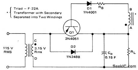
Half-wave synchronous rectification circuit (courtesy Motorola Semiconductor Products Inc.). (View)
View full Circuit Diagram | Comments | Reading(599)
Automaticgain_control_circuit
Published:2009/7/21 3:19:00 Author:Jessie

Automaticgain control circuit. The AD531 programmable multiplier/divider maintains a 3-volt peak-to-peak output for inputs from 0.1 volt to over 12 volts with 2% regulation for the range from 0.4 volt peak to peak to 6 volts peak to peak. The input frequency can range from 30 hertz to 400 hertz (courtesy Analog Devices, Inc.). (View)
View full Circuit Diagram | Comments | Reading(629)
| Pages:954/2234 At 20941942943944945946947948949950951952953954955956957958959960Under 20 |
Circuit Categories
power supply circuit
Amplifier Circuit
Basic Circuit
LED and Light Circuit
Sensor Circuit
Signal Processing
Electrical Equipment Circuit
Control Circuit
Remote Control Circuit
A/D-D/A Converter Circuit
Audio Circuit
Measuring and Test Circuit
Communication Circuit
Computer-Related Circuit
555 Circuit
Automotive Circuit
Repairing Circuit