Basic Circuit
PWM_SPEED_CONTROLAND_ENERGY_RECOVERING_BRAKE
Published:2009/7/8 4:48:00 Author:May | From:SeekIC

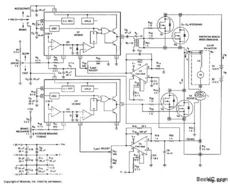
This circuit uses the main drive motor as a generator/brake to recover the battery charge during vehicle braking. When this is done, it can increase the overall range and efficiency of an electric vehicle.
In the accelerate mode, Q1 through Q3 receive gate pulses from U1, an on-line, current-mode, PWM controller IC. Assuming negligible effects of R, when Q1 through Q3 turn on, current I1 builds up through the motor at a rate of:
d/I1=VB-VA
where: VA = Battery voltage VB= Motor's back EMF LA = Motor inductance in henries
Motor current and torque continue to rise until the voltage on the ISENSE line is greater than IRESET, as determined by the speed potentiometer. At this time, Q1 through Q3 are switched off, current I2 begins to flow and decreases at a rate of: dI2 VA — = — dt LA
until the next clock period begins.As vehicle braking occurs, accelerate PWM IC U1 is switched off and braking PWM IC U2 and Q2 through Q4 are switched on. During this time, the back EMF source voltage causes current I3 to begin to flow at the rate of:
dI3 VA — = — dt LA
The current I3 continues to rise until ISENSE is greater than IRESET. Now, Q2 through Q4 are switched off and IB is forced to flow back into the storage battery, thus energy is recovered.
The braking torque produced by the motor is proportional to the average reverse current that flows through the motor on the duty cycle of Q2 through Q4. The braking force can continue until: VA =0
For reliable performance, voltage supplies should be independent of the main battery voltage.
Reprinted Url Of This Article:
http://www.seekic.com/circuit_diagram/Basic_Circuit/PWM_SPEED_CONTROLAND_ENERGY_RECOVERING_BRAKE.html
Print this Page | Comments | Reading(3)

Article Categories
power supply circuit
Amplifier Circuit
Basic Circuit
LED and Light Circuit
Sensor Circuit
Signal Processing
Electrical Equipment Circuit
Control Circuit
Remote Control Circuit
A/D-D/A Converter Circuit
Audio Circuit
Measuring and Test Circuit
Communication Circuit
Computer-Related Circuit
555 Circuit
Automotive Circuit
Repairing Circuit
Code: