
Circuit Diagram
Index 955
Automatic_level_control_circuit
Published:2009/7/21 3:17:00 Author:Jessie
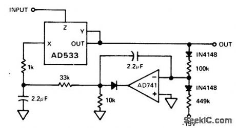
Automatic level control circuit. The AD533 is set up in the divide mode. Its output is rectified and compared with the power supply derived - 15volt reference. The net current is integrated by the AD741 and fed into the denominator input el the AD533, maintaining the level of the output at the AC average value programmed by the feedback circuitry, 7 volts in this case (courtesy Analog Devices, Inc.). (View)
View full Circuit Diagram | Comments | Reading(948)
AMFMAND_SWEEP
Published:2009/7/21 3:17:00 Author:Jessie

Oscillator and multiplier sections of Exar XR-S200 PLL IC are connected as general-purpose voltage-tuned AM/FM radio-frequency signal generator. Can also serve as high-stability carrier or reference generator if crystal at desired frequency is connected between pins 19 and 20 as shown. Multiplier section introduces amplitude modulation on carrier signal generated by VCO. Balanced multiplier allows suppressed-carrier or double-sideband modulation, Typical carrier suppression is above 40 dB for frequencies up to 10 MHz. With timing capacitor used in place of crystal, oscillator section can provide highly linear FM or frequency sweep. Digital control terminals of oscillator can be used for frequency-shift keying.- Phase-Locked Loop Data Book, Exar Integrated Systems, Sunnyvale, CA, 1978, p 9-16. (View)
View full Circuit Diagram | Comments | Reading(1180)
Battery_powered_load_cell_amplifier_for_discontinuous_service
Published:2009/7/21 3:16:00 Author:Jessie
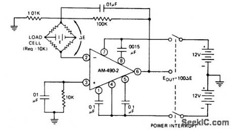
Battery-powered load-cell amplifier for discontinuous service. The AM-490-2 is an 8-pin TO-99 differential-input chopper-stabilized op amp. For power interrupt applications the amplifier has a warm-up period of 200 ms (courtesy Datel Systems, Inc.). (View)
View full Circuit Diagram | Comments | Reading(2659)
Percentage_computer_using_an_AD534_multiplier_divider_chip
Published:2009/7/21 3:15:00 Author:Jessie


Percentage computer using an AD534 multiplier/divider chip (courtesy Analog Devices, Inc.). (View)
View full Circuit Diagram | Comments | Reading(717)
Differential_amplifier_using_a_Datel_AM_490_28_pin_TO_99_chip
Published:2009/7/21 3:15:00 Author:Jessie
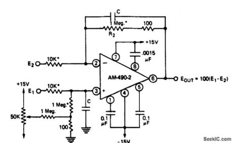
Differential amplifier using a Datel AM-490-28-pin TO-99 chip. For a 0.01% match between 1 M resistors and 10k resistors, common mode rejection ratio is approximately 120 dB. Capacitors Care used onlyto reduce bandwidth and hence output noise (courtesy Datel Systems, Inc.). (View)
View full Circuit Diagram | Comments | Reading(585)
Divider_circuit_using_an_AD532_multiplier_divider_chip
Published:2009/7/21 3:15:00 Author:Jessie

Divider circuit using an AD532 multiplier/divider chip. The AD532 is available as a 10-pin TO-100 or as a 14-pin DIP (courtesy Analog Devices, Inc.). (View)
View full Circuit Diagram | Comments | Reading(872)
TV_video_IF_amplifier_using_an_ECG1128_7_pin_module
Published:2009/7/21 4:10:00 Author:Jessie
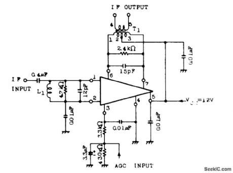
TV video IF amplifier using an ECG1128 7-pin module. Typical power gain is 48 dB. Maximum output voltage is 180 mV (courtesy GTE Sylvania Incorporated). (View)
View full Circuit Diagram | Comments | Reading(608)
PHOTOGRAPHIC_DRYER_CONTROL
Published:2009/7/21 4:09:00 Author:Jessie

Copper drum, serving as single-turn shorted secondary of transformer, is heated by several thousand amperes of induced current. As drum heats up, transformer primary current decreases. When desired temperature is reached, KA energizes and T1 is disconnected by KB.-D. A. Senior, Temperature Control for Hot Rollers in Industry, Electronics, 32:30, p 40-42. (View)
View full Circuit Diagram | Comments | Reading(781)
Squarer_circuit_using_an_AD533_multiplier_divider_chip
Published:2009/7/21 4:09:00 Author:Jessie
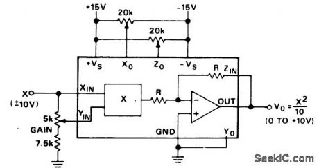
Squarer circuit using an AD533 multiplier/divider chip. With X at zero volts adjust Zo for a zero-volt DC output. With X equal to +10 volts DC adjust gain for +10 volts DC output. Reverse the polarity of X input and adjust Xo to reduce the output error to half its original value and adjust gain to take out the remaining error. Check the output offset with the input grounded. If nonzero repeat the above procedure (courtesy Analog Devices, Inc.). (View)
View full Circuit Diagram | Comments | Reading(998)
TV_FM_sound_IF_with_tube_type_audio_output_stage
Published:2009/7/21 4:09:00 Author:Jessie

TV FM sound IF with tube-type audio output stage. The ECG710 contains a multistage wide-band amplifier section, a zener-regulated power supply section, and an AF amplifier section (courtesy GTE Sylvania Incorporated). (View)
View full Circuit Diagram | Comments | Reading(695)
MAGNIFICATION_COMPENSATING_DARK_ROOM_TIMER
Published:2009/7/21 4:07:00 Author:Jessie

Pushbutton timer provides automatic compensation of exposure time with magnification of negative.-J. Markus and V. Zeluff, Handbook of Industrial Electronic Control Circuits, McGraw-Hill, N.Y., 1956, p 296. (View)
View full Circuit Diagram | Comments | Reading(800)
A_D_dividers_using_the_AD7520_18_pin_DIP
Published:2009/7/21 4:07:00 Author:Jessie

A/D dividers using the AD7520 18-pin DIP. With all bits off the amplifier saturates since division by zero isn’t defined. With the LSB (bit 10) on the gain is 1023. With all bits on the gain is 1 (courtesy Intersil, Inc.). (View)
View full Circuit Diagram | Comments | Reading(749)
TV_sound_channel_with_1_watt_output_using_an_ECG807
Published:2009/7/21 4:06:00 Author:Jessie

TV sound channel with 1-watt output using an ECG807. The circuit features DC volume control with 70 dB attenuation typical, limiter gain of 70 dB, limiting threshold at 200 μV, automatic thermal shutdown, and audio output short-circuit protection. The circuit will drive 8-, 16- or 32 -ohm speaker loads and provide a true 1-watt output with an 8-ohm load (courtesy GTE Sylvania Incorporated). (View)
View full Circuit Diagram | Comments | Reading(743)
TV_FM_sound_IF_with_transistor_power_output_stage
Published:2009/7/21 4:05:00 Author:Jessie

TV FM sound IF with transistor power output stage. The ECG710 contains a multisection wide-band IF amplifier, a zener-regulated power supply section, and an AF amplifier section (courtesy GTE Sylvania Incorporated). (View)
View full Circuit Diagram | Comments | Reading(767)
Vector_computation_circuit_for_VSUBC_SUBSUP2_SUP__=_VSUBA_SUBSUP2_SUP____VSUBB_SUBSUP2_SUP__using_the_434_multiplier_divider_chip_and_two_AD741_op_amps
Published:2009/7/21 4:05:00 Author:Jessie

Vector computation circuit for VC2 = VA2 + VB2 using the 434 multiplier/divider chip and two AD741 op amps (courtesy Analog Devices, Inc.). (View)
View full Circuit Diagram | Comments | Reading(583)
KERR_CELL_SHUTTER
Published:2009/7/21 4:04:00 Author:Jessie

High-voltage Kerr-cell pulser and parallel triggering synchronization give 5-nsec exposure, with triggering time jitter less than 1 nsec. Power supply must deliver 350-amp pulse as 35 kv.-S. M. Hauser and H. Quan, Applying the Kerr Cell to Nanosecond Photography, Electronics, 34:33, p 56-59. (View)
View full Circuit Diagram | Comments | Reading(1113)
PHOTOMULTIPLIER_TIMER_FOR_ENLARGER
Published:2009/7/21 4:02:00 Author:Jessie

Quartet-watt neon lamps regulate dynode potentials. Graded-capacitor voltage divider across string of neons makes them fire in sequence, to eliminate variations in firing times and increase timing accuracy.-J. Markus and V. Zeluff, Handbook of Industrial Electronic Control Circuits, McGraw-Hill, N.Y., 1956, p 297. (View)
View full Circuit Diagram | Comments | Reading(824)
45_MHz_sound_section_for_TV_using_one_ECG7O6_IC
Published:2009/7/21 4:00:00 Author:Jessie

4.5 MHz sound section for TV using one ECG706 IC.The chip contains a wide-band IF amplifier-limiter section,an FM detector stage,a zener regulated power Supply section,and an audio amplifier section specifically designed todrive a 6AQ5(courtesy GTE Sylvania Incorporated). (View)
View full Circuit Diagram | Comments | Reading(1566)
Square_rooter_using_an_AD533_multiplier_divider_chip
Published:2009/7/21 4:23:00 Author:Jessie

Square rooter using an AD533 multiplier/divider chip. With Z equal to +0.1 volt DC adjust ZO for a-1.0 volt DC output. With Z equal to +10.0 volts DC adjust gain for-10.0 volts DC output.With Z equal to +2.0 volts DC adjust Xo for a -4.47±0.1 volt DC output (courtesy Analog Devices,Inc.). (View)
View full Circuit Diagram | Comments | Reading(732)
Divider_circuit_with_digitally_controlled_gain_1
Published:2009/7/21 4:22:00 Author:Jessie

Divider circuit with digitally controlled gain (courtesy Analog Devices, Inc.). (View)
View full Circuit Diagram | Comments | Reading(667)
| Pages:955/2234 At 20941942943944945946947948949950951952953954955956957958959960Under 20 |
Circuit Categories
power supply circuit
Amplifier Circuit
Basic Circuit
LED and Light Circuit
Sensor Circuit
Signal Processing
Electrical Equipment Circuit
Control Circuit
Remote Control Circuit
A/D-D/A Converter Circuit
Audio Circuit
Measuring and Test Circuit
Communication Circuit
Computer-Related Circuit
555 Circuit
Automotive Circuit
Repairing Circuit