Position: Home > Circuit Diagram > Electrical Equipment Circuit > Squarer_circuit_using_an_AD533_multiplier_divider_chip
Electrical Equipment Circuit
Squarer_circuit_using_an_AD533_multiplier_divider_chip
Published:2009/7/21 4:09:00 Author:Jessie | From:SeekIC

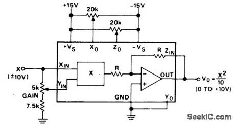
Squarer circuit using an AD533 multiplier/divider chip. With X at zero volts adjust Zo for a zero-volt DC output. With X equal to +10 volts DC adjust gain for +10 volts DC output. Reverse the polarity of X input and adjust Xo to reduce the output error to half its original value and adjust gain to take out the remaining error. Check the output offset with the input grounded. If nonzero repeat the above procedure (courtesy Analog Devices, Inc.).
Reprinted Url Of This Article:
http://www.seekic.com/circuit_diagram/Electrical_Equipment_Circuit/Squarer_circuit_using_an_AD533_multiplier_divider_chip.html
Print this Page | Comments | Reading(3)

Article Categories
power supply circuit
Amplifier Circuit
Basic Circuit
LED and Light Circuit
Sensor Circuit
Signal Processing
Electrical Equipment Circuit
Control Circuit
Remote Control Circuit
A/D-D/A Converter Circuit
Audio Circuit
Measuring and Test Circuit
Communication Circuit
Computer-Related Circuit
555 Circuit
Automotive Circuit
Repairing Circuit
Code: