
Circuit Diagram
Index 948
Variable_audio_oscillator_with_a_range_of_20_hertz_to_20_kilohertz
Published:2009/7/20 23:04:00 Author:Jessie

Variable audio oscillator with a range of 20 hertz to 20 kilohertz. The chip used is an Intersil 8038 waveform generator, which is a 14-pin DIP (courtesy Intersil, Inc.). (View)
View full Circuit Diagram | Comments | Reading(1993)
800_kHz_experimental_BF_oscillator_using_an_LM3909_chip
Published:2009/7/20 23:03:00 Author:Jessie

800 kHz experimental BF oscillator using an LM3909 chip. Circuitry inside the dashed lines is the LM3909. The external coil is a standard broadcast loopstick. The variable capacitor is 360 pF (courtesy National Semiconductor Corporation). (View)
View full Circuit Diagram | Comments | Reading(494)
Crystal_oscillator_with_amplitude_modulated_output
Published:2009/7/20 23:01:00 Author:Jessie

Crystal oscillator with amplitude-modulated output. The black box crystal oscillator output is converted to DC by the AD536 PMS/DC converter. The AD536 output is summed in the AD741 with the DC reference voltage obtained by inverting and amplifying the output of the AD580 band-gap reference. The AD741 drives the 2N2222 control transistor to close the feedback loop around the oscillator by adjusting its supply voltage. The AD534 serves as an amplitude modulator. The oscilloscope waveforms show the 32.768 kHz signal being switched by a fast step from 0.3 to 2.2 volts peak to peak with no ringing, overshoot, etc. (courtesy Analog Devices, Inc.). (View)
View full Circuit Diagram | Comments | Reading(978)
163_MHz_oscillator_for_low_side_injection_in_CB_operation_using_a_TIS148_dualgate_MOSFET
Published:2009/7/20 22:59:00 Author:Jessie
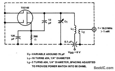
16.3 MHz oscillator for low-side injection in CB operation using a TIS148 dualgate MOSFET(courtesy Texas Instruments Incorporated).
(View)
View full Circuit Diagram | Comments | Reading(574)
PARALLEL_OPAMP_PREAMP
Published:2009/7/20 22:58:00 Author:Jessie

Provides differential output required for driving power amplifier of 115-V 60-Hz servomotor. One opamp section is connected inverting and the other noninverting to give required complementary outputs, Voltage gain is 40 dB, operating from single 20-V zener-regulated supply. High DC feedback gives excellent DC stability. Band-width is about 6 kHz. Input is driven by 90° phase shifter.-A. Pshaenich, Servo Motor Drive Amplifiers, Motorola, Phoenix, AZ, 1972, AN-590. (View)
View full Circuit Diagram | Comments | Reading(866)
Low_distortion_oscillator
Published:2009/7/20 22:58:00 Author:Jessie

Low-distortion oscillator. A1 is connected as a noninverting amplifier and has again of three. As shown the oscillator output is 1 kHz, determined by R1, R5, C1 and C2. See equation in diagram to determine frequency (courtesy Analog Devices, Inc.). (View)
View full Circuit Diagram | Comments | Reading(2067)
105_MHz_to_107_MHz_mixer
Published:2009/7/20 22:58:00 Author:Jessie
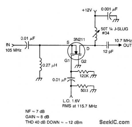
105 MHz to 10.7 MHz mixer (courtesy Texas Instruments Incorporated). (View)
View full Circuit Diagram | Comments | Reading(700)
28_V_PUSH_PULL_POWER_AMPLIFIER
Published:2009/7/20 22:57:00 Author:Jessie
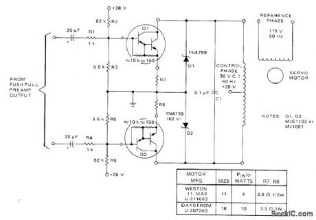
Power Darlingtons are used in common-emitter con-figuration to give high current gain for driving control phase of 60-Hz servo while providing high input impedance for preamp. No trans-formers are required. Darlingtons require heatsinks. Suitable for driving size 11 servo at 4 W and size 18 at 10 W if emitter resistors R7 and R8 are changed as in table.-A. Pshaenich, Servo Motor Drive Amplifiers, Motorola, Phoenix, AZ, 1972, AN-590. (View)
View full Circuit Diagram | Comments | Reading(654)
105_MHz_PF_amplifier_using_a_3N204_dual_gate_MOSFET
Published:2009/7/20 22:56:00 Author:Jessie
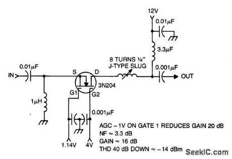
105 MHz PF amplifier using a 3N204 dual-gate MOSFET (courtesy Texas Instruments Incornorated). (View)
View full Circuit Diagram | Comments | Reading(694)
125_MHz_IF_amplifier_using_a_3N225_dual_gate_MOSFET
Published:2009/7/20 23:27:00 Author:Jessie
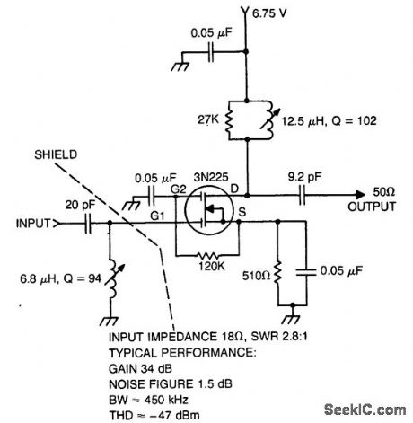
12.5 MHz IF amplifier using a 3N225 dual-gate MOSFET(courtesy Texas Instluments Incorporated). (View)
View full Circuit Diagram | Comments | Reading(613)
Linear_voltage_controlled_oscillator
Published:2009/7/20 23:26:00 Author:Jessie

Linear voltage-controlled oscillator (courtesy Intersil, Inc.) (View)
View full Circuit Diagram | Comments | Reading(1330)
27_MHz_autodyne_tuner_using_a_3N204_dual_gate_MOSFET
Published:2009/7/20 23:25:00 Author:Jessie
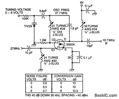
27 MHz autodyne tuner using a 3N204 dual-gate MOSFET (courtesy Texas Instruments Incorporated). (View)
View full Circuit Diagram | Comments | Reading(1080)
MUSCLE__POTENTIAL__TELEMETER
Published:2009/7/20 23:25:00 Author:Jessie

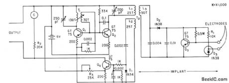
Implanted probe circuit receives power at 50 kc from external pickup coil driven by modified Hartley oscillator Q1. Signal is rectified by D2 to provide d-c power for Q3, to generate magnetic field that varies with muscle potential .-S. Bagno, F. Liebman, and F. Cosenza, Detecting Muscle Potentials in Unanesthetized Animals, Electronics, 33:41, p 58-59. (View)
View full Circuit Diagram | Comments | Reading(497)
Frequency_modulated_52_MHz_oscillator
Published:2009/7/20 23:24:00 Author:Jessie

Frequency-modulated 52 MHz oscillator. The circuit uses an MPS6511 transistor especially designed for oscillators. The 1N5146 is a varactor diode rated at 33 pF for are verse bias of -4volts. L2 and L3 are used to tune out unwanted harmonics. Audio inputs should be limited to 200 mV or less (courtesy Motorola Semiconductor Products, Inc.). (View)
View full Circuit Diagram | Comments | Reading(678)
PULSE_AMPLIFIER_FOR_HEART
Published:2009/7/20 23:23:00 Author:Jessie
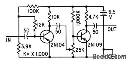
Used to provide adequate stimulating voltage to electrode sewn on ventricle of heart to make it contract properly in heart-blocked patients. Command pulses from electrode on auricle are amplified 200 times by circuit, without waveform distortion, and applied to ventricle electrodes to produce normal pumping rhythm.-G. F. Vanderschmidt, Two-Transistor Amplifier Corrects Heart Block, Electronics, 31:47, p 80-81. (View)
View full Circuit Diagram | Comments | Reading(550)
45_MHz_58_MHz_RF_amplifier
Published:2009/7/20 23:23:00 Author:Jessie
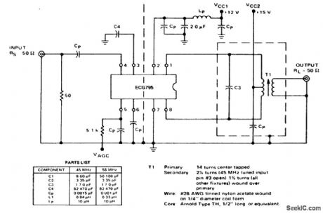
45 MHz/58 MHz RF amplifier. See listing for component values (courtesy GTE Sylvania Incorporated). (View)
View full Circuit Diagram | Comments | Reading(552)
RETINA_WELD_TIMER
Published:2009/7/20 23:22:00 Author:Jessie
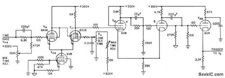
Time base ramp volt-age is fed to trigger pickoff circuit V16-V17-V19A. Delay time potentiometer R4 deter-mines voltage at which V17 conducts. Delayed pulse is fed to trigger-shaping mvbr V18 which feeds strong, fast pulse to V198 to give output for firing thyratron that turns off r-f power.-O. Rich, Jr. and R. V. Hill, R-F Spot Welder Reattaches Retina of Human Eye, Electronics, 34:32, p 160-163. (View)
View full Circuit Diagram | Comments | Reading(657)
45_MHz_58_MHz_BF_ampllfier_with_tuned_input
Published:2009/7/20 23:22:00 Author:Jessie
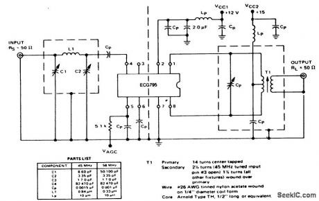
45 MHz/58 MHz BF ampllfier with tuned input.See listing for component values(courtesy GTE Sylvania Incorporated). (View)
View full Circuit Diagram | Comments | Reading(594)
105_MHz_crystal_oscillator_operating_at_the_fifth_overtone
Published:2009/7/20 23:21:00 Author:Jessie


105 MHz crystal oscillator operating at the fifth overtone (courtesy Texas Instruments Incorporated). (View)
View full Circuit Diagram | Comments | Reading(760)
FM_wireless_microphone_using_and_ECG1014_and_ECG1017
Published:2009/7/20 23:19:00 Author:Jessie
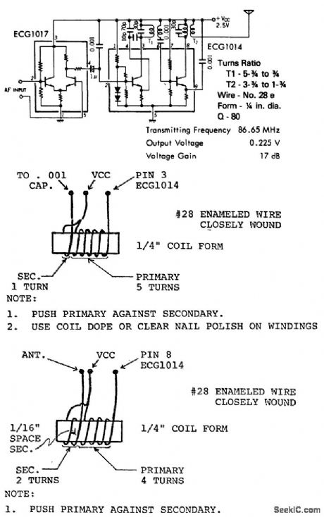
FM wireless microphone using and ECG1014 and ECG1017. Circuit works well up to 250 to 300 feet. For maximum stability cement coil forms to chassis or board. Recommended supply voltage is 4.5 volts using three cells (courtesy GTE Sylvania Incorporated). (View)
View full Circuit Diagram | Comments | Reading(711)
| Pages:948/2234 At 20941942943944945946947948949950951952953954955956957958959960Under 20 |
Circuit Categories
power supply circuit
Amplifier Circuit
Basic Circuit
LED and Light Circuit
Sensor Circuit
Signal Processing
Electrical Equipment Circuit
Control Circuit
Remote Control Circuit
A/D-D/A Converter Circuit
Audio Circuit
Measuring and Test Circuit
Communication Circuit
Computer-Related Circuit
555 Circuit
Automotive Circuit
Repairing Circuit