Amplifier Circuit
_PWM_SERVO_AMPLIFIER
Published:2009/7/8 4:43:00 Author:May | From:SeekIC

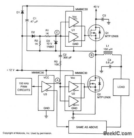
A major feature of the PWM servo amplifier is elimination of a pulse transformer. A 150 kHz pulse-width modulated signal is applied to U3, with its complementary outputs applied to identical circuits to drive the load. When point A increases, Q2 is on and point B is at ground potential. The VCC, for U1 is maintained through D1, and Q1 is held off by D2. When point A decreases,Q2 turns off, point C is pulled low by C2, which turns Q1 on. The time constant for R1, R3, and C2 can hold Q1 on just long enough to allow the voltage at point B to start rising. As point B rises, it charges C2 by forward biasing D3, maintaining point C low with respect to U1, and keeping Q1 turned on.
With point B at 40 V, D2 is off and point C is held low by R1 and R2, and VCC for U1 is maintained by the charge on C1. When point A increases again, Q2 again turns on, C2 pushes point C high, and turns Q1 off long enough to allow the voltage at point B to start falling. C2 is now discharged by reverse-biased D3, which keeps point C high with respect to U1, and keeps Q1 off. Once point B reaches ground potential, D1 again turns on, recharging C1, and maintaining VCC to U1. D2 also turns on and keeps Q1 off.
Reprinted Url Of This Article:
http://www.seekic.com/circuit_diagram/Amplifier_Circuit/_PWM_SERVO_AMPLIFIER.html
Print this Page | Comments | Reading(3)

Article Categories
power supply circuit
Amplifier Circuit
Basic Circuit
LED and Light Circuit
Sensor Circuit
Signal Processing
Electrical Equipment Circuit
Control Circuit
Remote Control Circuit
A/D-D/A Converter Circuit
Audio Circuit
Measuring and Test Circuit
Communication Circuit
Computer-Related Circuit
555 Circuit
Automotive Circuit
Repairing Circuit
Code: