Electrical Equipment Circuit
SERVO_DRIVE
Published:2009/7/20 22:40:00 Author:Jessie | From:SeekIC

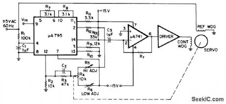
Combination of Fairchild μA795 multiplier and μA741 opamp generates AC error signal for driving two-phase servo-motor. Phase-shifted signal from R1-C1 is applied to input pin 4 of multiplier, DC signal input is applied to pin 9, and servo position signal goes to pin 12. Multiplier takes difference between signals on 9 and 12, multiplies this by signal on pin 4, and feeds resulting sine wave from pin 14 to opamp for amplification and transfer to servo driver. When servomotor action makes voltages on 9 and 12 equal, system is nulled.-Fairchild Linear IC Contest Winners, EEE Magazine, Jan. 1971, p 48-49.
Reprinted Url Of This Article:
http://www.seekic.com/circuit_diagram/Electrical_Equipment_Circuit/SERVO_DRIVE.html
Print this Page | Comments | Reading(3)

Article Categories
power supply circuit
Amplifier Circuit
Basic Circuit
LED and Light Circuit
Sensor Circuit
Signal Processing
Electrical Equipment Circuit
Control Circuit
Remote Control Circuit
A/D-D/A Converter Circuit
Audio Circuit
Measuring and Test Circuit
Communication Circuit
Computer-Related Circuit
555 Circuit
Automotive Circuit
Repairing Circuit
Code: