
Circuit Diagram
Index 939
BRIDGE_TYPE_AC_SERVO_AMPLIFIER
Published:2009/7/8 5:08:00 Author:May
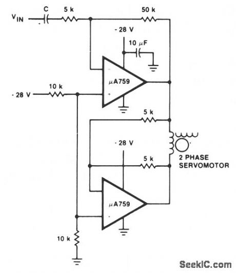
This motor driver circuit uses a μA759 power amplifter to drive a two-phase servomotor. (View)
View full Circuit Diagram | Comments | Reading(597)
DC_MOTOR_DRIVE_WITH_FIXED_SPEED_CONTROL
Published:2009/7/8 5:07:00 Author:May
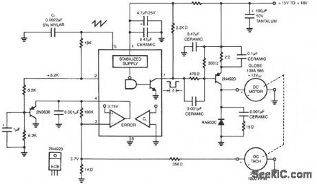
The NE5561 provides pulse-proportional drive and speed control based on dc tachometer feedback. This simple switching circuit consists of transistor 2N4920 pnp with a commutation diode used to deliver programmed pulse energy to the motor. A frequency of approximately 20 kHz is used to eliminate audio noise. The dc tach delivers 2.7V/1000 RPM. Negative feedback occurs when this voltage is applied to the error amplifier of the NE5561. The duty cycle varies directly with load torque demand. The no-load current is≈ 0.3 A and full load is 0.6 A. (View)
View full Circuit Diagram | Comments | Reading(2013)
5_DIGIT_THERM_OM_ETER
Published:2009/7/8 4:56:00 Author:May

Temperature-to-frequency converter drives digital display providing0 .001°C resolution with 0.15°C absolute accuracy, Linearized thermistor network biases inverting input of AD521J instrumentation amplifier, while noninverting input is driven from same reference. Output can be fed directly to analog strip-chart recorder or computer, in addition to providing 0-10 V feed (for 0-100°C) to voltage-to-frequency circuit that drives display.Readout is updated at 2-s intervals.-J. Wil-Iiams, Designer's Guide to: Temperature Measurement, EDN Magazine, May 20, 1977, p 71-77.
(View)
View full Circuit Diagram | Comments | Reading(651)
80_M_AMATEUR_RADIO_TRANSMITTER
Published:2009/7/8 4:55:00 Author:May
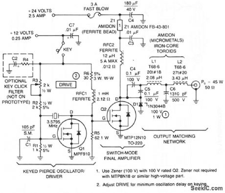
This transmitter consists of a keyed crystal oscillatoridriver and a high efficiency final, each with a TMOS Power FET as the active element. The total parts cost less than $20, and no special construction skills or circuit boards are required.The Pierce oscillator is unique because the high CRSS of the final amplifier power FET, 700 - 1200 pF, is used as part of the capacitive feedback network. In fact, the oscillator will not work without Q2 installed. The MPF910 is a good choice for this circuit because the transistor is capable of driving the final amplifier in a switching mode, while still retaining enough gain for oscillation. To minimize cost, a readily-available color burst TV crystal is used as the frequency-determining element for Q1.An unusual 84% output efficiency is possible with this transmitter. Such high efficiency is achieved because of the TMOS power FET's characteristics, along with modification of the usual algorithm for determining output matching. (View)
View full Circuit Diagram | Comments | Reading(1656)
AUTONATIC_FAN_SPEED_CONTROLLER
Published:2009/7/8 4:54:00 Author:May
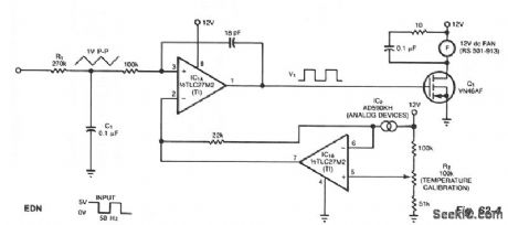
The controller circuit can reduce a fan's noise, power consumption, and wear, particularly in the presence of a low, fluctuating ambient temperature. Mount a temperature sensor in the fan's airstream, and the circuit will adjust the fan speed as necessary to maintain a relatively constant sensor temperature.Input components R1 and C1 integrate the input square wave, producing a quasitriangular wave at the noninverting input of op amp IC1A. At this inverting input is a reference voltage that decreases as temperature increases. The two-terminal sensor produces 1 μA/°K. The result is a rectangular wave at the output of IC1A with a duty cycle proportional to absolute temperature. Thus, a rise in temperature triggers a counter acting cooling effect by delivering more power to the fan. To calibrate the system with the sensor at room temperature, simply adjust R2 for a 50% duty cycle at V1. The fan will switch off at approximately 0℃ and will be fully on at 44℃. (View)
View full Circuit Diagram | Comments | Reading(590)
FM_AUTO_RADIO_IF
Published:2009/7/8 4:52:00 Author:May
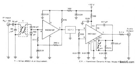
Uses MC1357 quadrature detector after ceramic filter to give IF bandwidth required for good stereo reproduction.Sensitivityis 18 μV for 3% total harmonic distortion.-''Integrated Circuit IF Amplifiers forAM/FM and FM Radios,'' Motorola,Phoenix,AZ,1975,AN-543A,p 6. (View)
View full Circuit Diagram | Comments | Reading(1633)
START_AND_RUN_MOTOR_CIRCUIT
Published:2009/7/8 4:52:00 Author:May

The timed two-voltage circuit can start and run a small dc motoror solenoid.The input voltage to the LM317 three-terminal regulator ranges from 5 to 40 V, and the output voltage can range from 2 to 36 V With input voltage VIN initially applied to the input,and capacitor C1 in a discharged state,the LM393 comparator's open-collector output circuit is open-circuited,Then the higher start-up output voltage is:
VOUT=1.25[1+(R3/240)]
At a time t after start-up,when:
t=-R1C1Ln[R4/(R4+R5)]or:
t=-R1C1,if R5=1.72R4
the comparator output decreases.At that time,the output voltage switches to a lower value to run thedevice at its proper operating level. (View)
View full Circuit Diagram | Comments | Reading(686)
THERMISTOR_THERMOMETER
Published:2009/7/8 4:51:00 Author:May

Thermistor for desired temperature range is one leg of Wheatstone bridge driving microammeter through transistor to provide direct indication of temperature. Can also be used for control purposes if suitable amplifier and relay are used in place of meter. Thermistor cable can be or-dinary parallel or twisted wires. To calibrate, immerse thermistor in water at various tem-peratures and measure water temperature with conventional high-accuracy thermometer. Cal-ibration graph can then be prepared as guidefor marking meter scale.-F. M. Mims, Transistor Projects, Vol. 1, Radio Shack, Fort Worth, TX, 1977, 2nd Ed., p 86-93. (View)
View full Circuit Diagram | Comments | Reading(3137)
LINE_OPERATED_POWER_OUTAGE_LIGHT
Published:2009/7/8 22:48:00 Author:Jessie
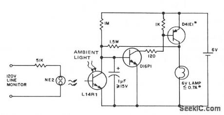
This circuit provides emergency lighting during a power outage. The phototransistor should be positioned to maximize coupling of both neon light and ambient light into the pellet, without allowing self-illumination from the 6-V lamp. Many circuits of this type also use line voltage to charge the battery.
(View)
View full Circuit Diagram | Comments | Reading(914)
Two_terminal__10_volt_reference
Published:2009/7/20 20:53:00 Author:Jessie
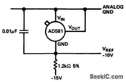
Two-terminal -10 volt reference (courtesy Analog Devices, Inc.). (View)
View full Circuit Diagram | Comments | Reading(549)
AUTOMATIC_BLOOD
Published:2009/7/20 20:52:00 Author:Jessie

High-gail amplifier-microphone combination detects pulse beats and feeds them through shaper circuit to hold-relays that lock pressure gages at systolic and diastolic blood-pressure readings.-R. J. Roy and M. Weiss, Inexpensive Monitor Reads Blood Pressure Automatically, Electronics, 35:47, p 40-41. (View)
View full Circuit Diagram | Comments | Reading(768)
15__20__25__35__50__60_watt_AF_power_amplifier_with_AC_coupled_output
Published:2009/7/20 20:52:00 Author:Jessie

15-/20-/25-/35-/50-/60-watt AF power amplifier with AC-coupled output (courtesy Motorola Semiconductor Products Inc.). (View)
View full Circuit Diagram | Comments | Reading(893)
Two_component_precision_current_limiter
Published:2009/7/20 20:52:00 Author:Jessie
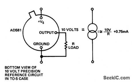
Two-component precision current limiter (courtesy Analog Devices, Inc.). (View)
View full Circuit Diagram | Comments | Reading(556)
TV_SOUND_SLOPE_DETECTOR
Published:2009/7/20 20:52:00 Author:Jessie

Uses drift transistor as efficient, highly sensitive oscillating linear-slope detector, injection-locked by one stage sound driver. A-m rejection is uniformly high over full detector bandwidth. Audio output is constant, independent of carrier strength.-M. Meth, Tv Sound Detector Uses Drift Transistor, Electronics, 32:8, p 62-64. (View)
View full Circuit Diagram | Comments | Reading(943)
Negative_voltage_regulators_for_5_6_12_or_15_volts_using_the_ECG9XX_series
Published:2009/7/20 20:52:00 Author:Jessie
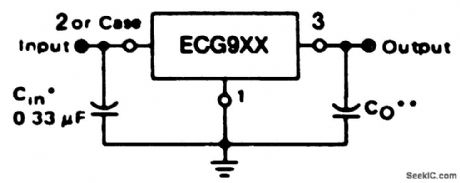
Negative voltage regulators for 5, 6, 12, or 15 volts using the ECG9XX series. Ratings for the three-terminal ECG9XX negative voltage regulators are as follows: ECG961, 5 volts; ECG963, 6 volts; ECG967, 12 volts; ECG969, 15 volts. A common is required between the input and output voltages. The input must remain 2 volts more negative than the output even during the high point on the input ripple voltage. These devices will handle up to 1 ampere without any heat sink. The input capacitor should be 0.33 μF if a tantalum or Mylar type is used. If an aluminum capacitor is used it should be 1.0 μF or larger (courtesy GTE Sylvania Incorporated). (View)
View full Circuit Diagram | Comments | Reading(707)
TELEPRINTER_CONTROL
Published:2009/7/20 20:51:00 Author:Jessie

Coded pulse train controls teleprinter. When negative pulses are applied to grid of V2, line relays open in correspondence to pulse pattern.-R. L. Thomas, R. Howat, and N. H. Mackworth, Tv Tracker Records Eye Focus Points, Electronics, 33:17, p 57-59. (View)
View full Circuit Diagram | Comments | Reading(700)
DELTA_TV_SOUND
Published:2009/7/20 20:51:00 Author:Jessie

Costs less than ratio derector sound system. Uses discriminator circuit with triode operating us power detector, with cancellation of undesired aim fundamental.-R. B. Dome, Inexpensive Sound for Television Receivers, Electronics, 32:9, p 66-68. (View)
View full Circuit Diagram | Comments | Reading(764)
TUNED_PLATE_TRIODE_POWER_OSCILLATOR
Published:2009/7/20 20:51:00 Author:Jessie

Drives ultrasonic transducer at odd harmonically related frequencies in 900 kc to 5 Mc optimum range, for neurosurgery, al power levels within 1 db of any prescribed level between 0.05 and 100 acoustic walls, without correction of amplitude after radiation has begun.-B. J. Cosman and T. F.Hueler, Instrumentation for Ultrasonic Neuro-surgery, Electronics, 32:200, p 53-57. (View)
View full Circuit Diagram | Comments | Reading(657)
Negative_switching_regulator_15_volts_using_an_ECG915_or_ECG915D_IC
Published:2009/7/20 20:50:00 Author:Jessie
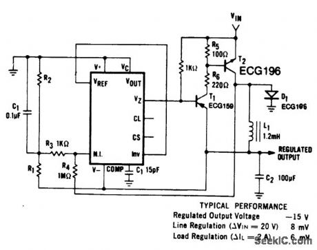
Negative switching regulator (15 volts) using an ECG915 or ECG915D IC. For a ±5% fixed output R1 is 3.65 ohms and R2 is 11.5 ohms. in metal can applications where Vz is required, connect a 6.2-volt zener in series with the regulated output.L1 is forty turns of AWG #20 enameled copper wire wound on Ferroxcube P36/22-387 pot core or equivalent with 0.009-inch air gap (courtesy GTE Sylvania Incorporated). (View)
View full Circuit Diagram | Comments | Reading(623)
OUTLINE_GENERATOR_FOR_TV_STUDIO
Published:2009/7/20 20:50:00 Author:Jessie

Produces variable-size rectangles in any desired position on tv screen, including horizontal or vertical white lines, for emphasizing particular part of picture during educational tv broadcast.-G. Southworth, Outline Generator for Educational Television, Electronics, 32:14, p 52-53. (View)
View full Circuit Diagram | Comments | Reading(668)
| Pages:939/2234 At 20921922923924925926927928929930931932933934935936937938939940Under 20 |
Circuit Categories
power supply circuit
Amplifier Circuit
Basic Circuit
LED and Light Circuit
Sensor Circuit
Signal Processing
Electrical Equipment Circuit
Control Circuit
Remote Control Circuit
A/D-D/A Converter Circuit
Audio Circuit
Measuring and Test Circuit
Communication Circuit
Computer-Related Circuit
555 Circuit
Automotive Circuit
Repairing Circuit