Control Circuit
AUTONATIC_FAN_SPEED_CONTROLLER
Published:2009/7/8 4:54:00 Author:May | From:SeekIC

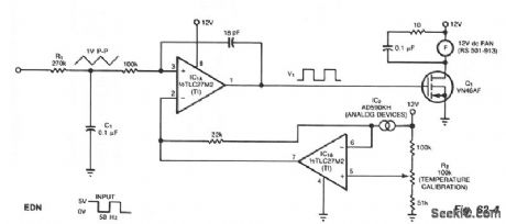
The controller circuit can reduce a fan's noise, power consumption, and wear, particularly in the presence of a low, fluctuating ambient temperature. Mount a temperature sensor in the fan's airstream, and the circuit will adjust the fan speed as necessary to maintain a relatively constant sensor temperature.Input components R1 and C1 integrate the input square wave, producing a quasitriangular wave at the noninverting input of op amp IC1A. At this inverting input is a reference voltage that decreases as temperature increases. The two-terminal sensor produces 1 μA/°K. The result is a rectangular wave at the output of IC1A with a duty cycle proportional to absolute temperature. Thus, a rise in temperature triggers a counter acting cooling effect by delivering more power to the fan. To calibrate the system with the sensor at room temperature, simply adjust R2 for a 50% duty cycle at V1. The fan will switch off at approximately 0℃ and will be fully on at 44℃.
Reprinted Url Of This Article:
http://www.seekic.com/circuit_diagram/Control_Circuit/AUTONATIC_FAN_SPEED_CONTROLLER.html
Print this Page | Comments | Reading(3)

Article Categories
power supply circuit
Amplifier Circuit
Basic Circuit
LED and Light Circuit
Sensor Circuit
Signal Processing
Electrical Equipment Circuit
Control Circuit
Remote Control Circuit
A/D-D/A Converter Circuit
Audio Circuit
Measuring and Test Circuit
Communication Circuit
Computer-Related Circuit
555 Circuit
Automotive Circuit
Repairing Circuit
Code: